© KROHNE 09/2003 7.02239.22.
Contents Nameplate ...................................................................................................................................... 3 Range of application ..................................................................................................................... 3 Product liability and warranty ...................................................................................................... 3 General safety information ...................................................
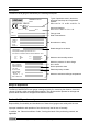
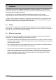
Nameplate The BM 102 level gauge is identified by the following nameplate. KROHNE S.A. Romans France MICROFLEX BM102 0344 KEMA No. 00ATEX1101 X II II Approved Category: Ex II 1/2 D T 100°C or Ex II 1 G T6...T4 EEx ia Types of protection used in the device; approved Gas Group and Temperature Classes EEx ia IIC T6…T3 or EEx ia IIB T6…T3 TYPE Full type code MANUFACT Date of manufacture N° comm. COMM.-No. N° Rep. Not relevant to safety TAG No. N° Fab. SERIAL No.
General safety information These Supplementary Instructions may only be used in conjunction with the standard Installation and Operating Instructions for the BM 102 level gauge. If you do not have these standard Instructions, please contact your nearest KROHNE office. Special regulations are applicable to the use of equipment in hazardous locations, and these are described in these Supplementary Instructions (supplied only with “Ex” devices).
1 Main safety-relevant characteristics 1.1 Approved categories Plastic-coated probes may not be used in connection with Gas Group IIC substances. 1.1.1 1 G The BM 102 level gauges are installed in areas requiring Category 1 G equipment. The devices are suitable for use in explosive atmospheres of all flammable substances of Gas Groups IIA, IIB and IIC. 1.1.2 1/2 G and 1/2 D The signal converter is installed in hazardous locations requiring Category 2 G or 2 D equipment.
The connected equipment may not exceed the following maximum safety values of the BM 102 devices: Ui ≤ 30 V Ii ≤ 150 mA Pi ≤ 1.0 W In addition, the inner self-inductance and self-capacitance of the BM 102 Co ≤ 10 nF Lo ≤ 10 µH must be included in the rating of the total inductance and total capacitance connected to the equipment. The calculated values may not exceed the values Co and Lo indicated on the supply equipment. 1.
1.4 Allowable temperatures 1.4.
1.4.3 Surface temperature For applications requiring Category 1/2 D or 2 D equipment, • with a dust layer of ≤ 5 mm, and • a process temperature of ≤ 200°C the surface temperature of the housing is max. 100°C.
2 Installation In accordance with current installation standards for hazardous locations (e.g. EN 60079-14 / VDE 0165), assembly and installation may only be carried out by specialist personnel who have received training in explosion protection. The notes given in the Standard Installation and Operating Instructions and in these Supplementary Instructions and the EC Type Test Certificate shall be observed without fail.
3 (Initial) Start-up Disconnect from power before starting work! Check the following points before device start-up: • Do probe, flange, gaskets and PTFE (included in all versions) have adequate corrosion resistance to the tank product? • Do the data on the nameplate of the signal converter agree with your operating data? • Check that the measuring device has been properly installed on the tank.
5 Service / Maintenance The device normally requires no maintenance when used for the intended purpose and for standard applications. 5.1 Signal converter The signal converter electronic equipment is maintenance-free under normal operating conditions and when used for the intended purpose.
Attachment 1 12 Statement of Conformity to ISO/IEC Guide 22 Supplementary Installation and Operating Instructions BM 102 ATEX
Attachment 2 EC Type Test Certificate KEMA 00ATEX1101 X Supplementary Installation and Operating Instructions BM 102 ATEX 13
Supplementary Installation and Operating Instructions BM 102 ATEX
If you need to return a device for testing or repair to KROHNE Your instrument has been carefully manufactured and tested. If installed and operated in accordance with these operating instructions, your instrument will rarely present any problems.