
User Manual
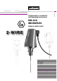

Supplementary Installation and Operating Instructions BM 102 ATEX 9
2 Installation
In accordance with current installation standards for hazardous locations (e.g. EN 60079-14 /
VDE 0165), assembly and installation may only be carried out by specialist personnel who have
received training in explosion protection.
The notes given in the Standard Installation and Operating Instructions and in these
Supplementary Instructions and the EC Type Test Certificate shall be observed without fail.
In addition, when installing the BM 102 for applications requiring Category 1G equipment, make
absolutely sure that there is no possibility of sparking due to blows or of any frictional stressing
between the signal converter housing and other metal parts.
2.1 Probes
The various probe types shall be installed such that they cannot come into contact with the tank
wall, and that, in consideration of internals and flow conditions in the tank, buckling or breakage of
the probes can be ruled out with sufficient certainty.
2.2 Electrical connection
The electrical connection of the BM 102 level gauges is effected as described in the standard
Instructions. The following additional points should be observed:
• Only certified intrinsically safe equipment may be connected to the supply terminals. Be aware
of the permissible maximum values. This requirement also applies if the device is not operated
in the hazardous location!
• The connecting cable for the intrinsically safe circuits is to be selected in accordance with the
valid installation standard (e.g. EN 60079-14 / VDE 0165).
• The device must be incorporated in the equipotential bonding system of the hazardous
location. This can be done by way of an appropriately conductive connection between the
device flange system and the tank. Where connection to the equipotential bonding system is
made via a separate conductor, this must be connected to the outer press-fitted U-clamp
terminal on the signal converter flange.