© KROHNE 03/2004 7.02229.33.00 GR Installation and Operating Instructions BM 102 MICROFLEX T D R Level gauge 2-WIRE Variable area flowmeters Vortex flowmeters Flow controllers Electromagnetic flowmeters Ultrasonic flowmeters Mass flowmeters Level measuring instruments Communications technology Engineering systems & solutions Switches, counters, displays and recorders Heat metering Pressure and temperature Subject to change without notice.
Table of contents 1 1.1 1.2 1.3 1.3.1 1.3.2 1.3.3 1.3.4 1.3.5 Mechanical installation .....................................................................................................5 Handling and storage ..........................................................................................................5 Installation restrictions .........................................................................................................7 Mounting on the tank ......................................
Device description and range of applications The BM 102 MICROFLEX level gauge uses the Time Domain Reflectometry (TDR) measuring principle and two-wire technology for level measurement. It is designed solely for measuring the distance, level, volume and ullage of liquids, pastes, slurries and powders. It can continue to measure the level or distance of the top product and total volume in applications with two or more products.
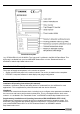
Standard nameplate *eg. VF030415B0112110110100000. The “type code” is defined in the BM 102 Data Sheet. This document is available from your local KROHNE Sales office or in the “Download Centre” on KROHNE’s website http://www.krohne.com/. Items included with supply The scope of supply encompasses, in the version as ordered: • Signal converter with probe in the version ordered. The version is stated on the nameplate. • PCSTAR 2 computer software for data display and gauge configuration.
Product liability and warranty: The BM 102 TDR level gauge is designed for measuring the distance, level, and volume of liquids, pastes, slurries, powders and cereal products. It may equally measure level, distance and total volume in applications with two or more products. Special codes and regulations apply to its use in hazardous areas : please refer to the BM 102 MICROFLEX KEMA 00 ATEX 1101X Supplementary Installation and Operating Instructions for further information.
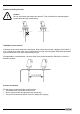
Avoiding blows When handling the BM 102, avoid hard blows, jolts, impacts, etc. Caution: Fragile electronics Avoid bending (single rod and coaxial probes) Support the probe to avoid bending. Support probe here Avoid cable kinks and fraying Do not coil the cable less than 400 mm or 16 “ in diameter. Cable kinks or fraying will cause measurement errors. Storage temperature Store within the given storage temperature limits.
1.2 Installation restrictions Hazardous-duty systems (Ex, FM,…) • Refer to the BM 102 MICROFLEX KEMA 00 ATEX 1101X Supplementary Installation and Operating Instructions supplementary instructions for further information on installing gauges approved for use in hazardous locations. This document is available from your local KROHNE Sales office or on the “Download Centre” on KROHNE’s website http://www.krohne.com/. • Check that the flange, gasket and probe materials are compatible with the product.
Nozzles extending into tank Caution: Do not use nozzles that extend into the tank. This will disturb the electromagnetic emitted pulse and the measurement. Installation of two devices If two devices are to be used on the same tank, these should be mounted a distance of at least 2 m or 6 ¾ ft away from each other. If not, interferences from the electromagnetic (EM) fields generated by both instruments may cause measurement errors.
Process connection and entry pipe Caution: Do not put the nozzle close to the entry pipe. Pouring the product directly onto the probe will give false readings. Install deflector plate if impossible to distance gauge from entry pipe. Stilling wells Tanks with floating roofs for petro-chemical applications: use a stilling well. 1 Stilling well 2 Tank 3 Floating roof 4 Product (petroleum applications) 5 Well fixed to tank base (no roof deformation) 6 Sediment 1.3.
Installation of level meters with single or twin cable probes 1 2 Caution : Do not over-bend probe! Inserting the probe: hold more than one metre above the opening to avoid cable bending. Probes: entanglement, straightness and tank bottom clearance Rigid section length of single and twin cable probes Cable diameter Rigid section length Single cable Ø4mm/0.15” 40mm or 1½” Ø4mm/0.15” 200mm or 8” Twin cable Ø4mm/0.15” 40mm or 1½” • • Cable probes must be straight once inserted into the tank.
For clean applications only : Coaxial (type 3) probes may be used close to or touching objects or walls as the EM field generated by the probe is contained within the probe’s outer sheath (refer also to the EM field sizes/free area given in the figures on the next page).
Avoid direct solar radiation Fit a sunshade on the gauge for open-air installations: this is either supplied on demand by KROHNE or provided by the customer. The ambient temperature limits of the gauge are given below. 1.3.
Fastening the probe to the tank bottom The flexible probe can be fastened with a chuck (ring) or a fastening device to the tank bottom: Chuck (ring) Turnbuckle for Ø8 mm cable probes Turnbuckle for Ø4 mm cable probes 1.3.
Conical silo nozzles, False readings and traction on the cable probes Caution 1 High traction forces : We recommend that the probe should not be anchored to avoid excessive traction loads on the cable. 2 Bending and traction: Position the connection on the roof at ½ radius of the tank and with minimum nozzle height. This will avoid damage due to bending and traction during emptying.
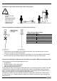
Electro static discharge (E.S.D.) BM 102 non-Ex and Ex gauge electronics are shielded up to 4kV against E.S.D.. Note: E.S.D. cannot be solved by BM 102 E.S.D. protection. It is the customer’s responsibility to avoid E.S.D. by grounding the tank, product and probe installation. 1 Danger of injury 2 The probe may receive an electrostatic discharge during operation; earth the probe by pushing it against tank wall with a suitably isolated tool just before touching it to avoid receiving a shock.
2 Electrical connections 2.1 Electrical installation instructions 2.1.1 Wiring general notes Connection to power is effected at the plug connector in the signal converter. Two wiring compartments are available: DIN connector or M16 terminal box. Observe applicable rules and regulations for cable connection: VDE 165 or equivalent national regulations. Always disconnect from power supply before opening wiring compartment. This is not mandatory for Exi applications.
2.1.3 Wiring connections: M16 terminal box Power terminals: Cable entry: Shielding: Wire cross-section: max. 1.5 mm² (AWG 16) 1 x M16 x 1.5, cable diameter: 3.5 … 8 mm or 0.14” … 0.31”, IP65 or NEMA4. For USA: ½” NPT conduit connection Do not connect shielding to the terminal compartment. Hazardous-duty systems When used in hazardous areas, only one intrinsically safe power supply may be connected to terminals 1 and 2. Ground terminal E is not to be connected.
Load impedance Rloop Loop resistance, Rloop Min. Rloop Max. Rloop RHART resistance for HART® communication RHART + Rcable + Rammeter 0 ohms 750 ohms 250 ohms (recommended) Line A = minimum voltage at the BM 102 terminals Line B = voltage drop caused by a 250 ohm loop resistance Example for calculating the required power supply: The voltage drop is tested at 22 mA. U power min. 22 = 22 mA x load impedance + Uinput min. 22 U power min. 22 = 22 mA x 250 ohms + 10 V = 5.5 V + 10 V = 15.
3 User interface 3.1 Power-on and start-up The BM 102 is pre-configured in accordance to customer order specifications and measurements can be made immediately. A warm-up time of less than 23 seconds should be allowed for once connected and the power is switched on. 3.2 Available user interfaces Measurements may be taken using either: • PC STAR 2 software • HART® Handheld Communicator (HHC) • DA 06 local indicator 3.3 Included as standard with the instrument.
Installing and connecting the PCSTAR 2 software 1. Connect the HART® adapter (not included in supply) through a load impedance of 350 ohms maximum (for hazardous-duty purposes, fix to the non-intrinsically safe side of the repeater power supply unit) and plug it into a serial interface on your PC. The repeater power supply ® unit must have HART capability. 2. Installing the program: Access the files on the floppy disk supplied with the instrument and execute the file "setup.
® 3.3.2 HART Communicator Display and configuration can also be carried out via a HART® communicator. Operator control via this unit is described in detail in the operating instructions supplied with the HHC.
3.3.3 Local user display (instruments equipped with DIN connectors only) The BM 102 local indicator is available as an option. This fits onto the BM 102’s standard DIN connector. Data can be read from an LED display. The gauge configuration menu cannot be accessed with this option. For non-Ex applications only. Please refer to the DA 06 Supplementary instruction manual for further information. This is available on request from KROHNE.
3.4 Fault clearing Event Error messages “Tank full” status marker on*, reading frozen at max. or min. value “Tank empty” status marker on*, reading frozen at max. or min. value “Tank full” and “Level lost” status marker on*, reading frozen at max. or min. value “Level lost” status marker on*, reading is frozen “Reference not found” status marker on* “Level lost” and “Reference not found” status markers on*, reading frozen Fault Action No fault.
Event “Flange not found” status marker on* “Delay out of limits” status marker on*, reading is frozen. “Negative voltage error” status marker on* “VC01 voltage error ” status marker on* “VC02 voltage error” status marker on* “Reprogramming FPGA” status marker on* General operation The BM 102 indicates an incorrect level value. Instrument is not accurate when there are two or more phases in the tank.
Event Fault Electrical Connections and Communication Output Current Output value No power supply < 4 mA. Connection of the device is incorrect. The calibration of the current output is incorrect. Reads 22 mA. An error has occurred. The device is in its start-up phase. The value at the current output does not correspond to the value at the display ® (PC STAR 2 or HART communicator). The current output settings are incorrect. Data communication via the digital interface is not working.
4 Technical data 4.1 Technical data Application Range of applications Continuous level measurement of liquids, solids and powders Function and system design Measuring principle Equipment architecture Time domain reflectometry using a direct mode of measurement See section 4.
Repeatability Hysteresis Resolution Transient recovery time ± 2 mm or 0.08” none ± 1 mm or 0.04” The transient recovery time to 1% deviation from the final value amounts to approximately 4.6 times the programmed time constant. However, the transient recovery time may differ if changes in level are very rapid. Start-up time ≤ 23 seconds Long term drift This is within the specified error of measurement. Allow for thermal expansion coefficient in the case of liquids. Organic liquids: 0.
Construction materials Housing Probe Gasket Spacers (on twin probes) Aluminium with epoxy coating Refer to section 4.2.1: BM 102 mechanical options Viton, optionally Kalrez 6375 Refer to section 4.2.1: BM 102 mechanical options Weight Housing Single rod Ø8mm or Ø0.3” Single cable Ø4mm or Ø0.15” Twin cable Ø4mm or Ø0.15” Single cable Ø8mm or Ø0.3” Coaxial Ø28mm or Ø1.1” 2 kg or 4.4 lb 0.41 kg/m or 0.28 lb/ft 0,12 kg/m or 0.08 lb/ft 0.24 kg/m or 0.16 lb/ft 0.41 kg/m or 0.28 lb/ft 1,3 kg/m or 0.
BM 102 SS 316 / 316L Probe material Liquid * gauge with flange connection SS 316L Hastelloy C276 DN50 PN 25/40 2” ANSI 150 lbs 2” G / 2” NPT** 1.8 Ø200 mm or Ø8” ≤ 24 m or 79 ft. Minimum process DN50 PN 25/40 connection 2” ANSI 150 lbs 1” G / 1” NPT 1.4 Ø0 mm or Ø0 “ Free area (no obstructions or discontinuities) Minimum dielectric constant, εr ≤ 6 m or 20 ft. Range, max. Level SS 316 / 316L DN50 PN 25/40 2” ANSI 150 lbs 1½” G / 1½” NPT 2.1 Ø600 mm or Ø4” ≤ 24 m or 79 ft.
BM 102 ** higher on request None Counterweight (dimensions in mm) Gauge illiustration PTFE (if length > 1.5 m or 5 ft). Spacer material *** on request Ø45 x 60 (316L) Turnbuckle (316L) FEP moulded onto the cable. Coaxial Øext. 28 mm Twin cable Ø4 mm or 1.1” (Type 3) or 0.15” (Type 4) Probe (Type code) Ø25 x 100 (316L) Ø25 x 100 (HC22) Ø25 x 100 (HC276) Chuck (316L) Turnbuckle (316L) No spacer. Single cable Ø4 mm or 0.15” (Type 2) Liquid / Liquid Gas applications None No spacer.
4.2.2 Probe measurement limits * Displayed level and distance values displayed will depend on how and at what level the minimum and maximum gauge outputs have been configured. Probe type Probe measurement limits Top dead zone, Bottom dead A1 zone, A2 εr=80* εr=80* 300mm or 12” 20mm or 0.8” 300mm or 12” 20mm or 0.8” Top dead zone, A1 εr=2.4* 400mm or 15¾” 400mm or 15¾” Single rod (type 1) Single cable Ø4mm or Ø0.15” (type 2) Coaxial (type 3) 0mm or 0” 10mm or 0.
4.3 Gauge dimensions The drawing below illustrates standard gauge configurations and overall dimensions. Housing Standard, M16 terminal box* with flange Standard, DIN connector** with threaded connection High temperature version With inactive length*** Probe 3: Coaxial Ø 28 (1.1) 4: Twin cable Ø 4 (0.15) 2: Single cable Ø 4 (0.15) 1: Single rod Ø 8 (0.3) 6: Single cable Ø 8 (0.
Returning a device for testing or repair to KROHNE Your instrument has been carefully manufactured and tested. If installed and operated in accordance with these operating instructions, it will rarely present any problems. Should you nevertheless need to return an instrument for inspection or repair, please pay strict attention to the following points.