DWM 2000 D Operating instructions DWM 2000 Electromagnetic Flowmeter with LCD Indicator
Contents 1 Display data in operating mode…………………………………………………………………..3 2 Functions of the LCD indicator for the DWM 2000 D ………………………………………..4 2.1 Programmable parameters ………………………………………………………………………..4 2.1.1 Flow calibration ………………………………………………………………………4 2.1.2 Current output adjustment ………………………………………………………….4 2.1.3 Time constant ………………………………………………………………………..4 2.2 Electronics module checks ……………………………………………………………………..5 2.3 Programming structure (Software n° 1.02) ………………………………………………………5 2.3.
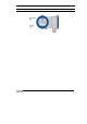
1 Display data in operating mode Operating Instructions DWM 2000 D 3
2 Functions of the LCD indicator for the DWM 2000 D 2.1 Programmable parameters 2.1.1 Flow calibration The GK can be modified in menu 2.1.3 in order to obtain the maximum accuracy at operating conditions. A field calibration requires an accurate reference of velocity. The meter recalibration (GK modification) is also recommended after an exchange of electronics module.
2.2 Electronics module checks Various parameters from the electronics module can be viewed directly for troubleshooting purposes. The DWM 2000 switches to alarm mode when the current output is permanently below 3 mA. In this case the current output value indicates the type of error that occurs: Obey the instructions that follow to find faults and the corrective actions to be undertaken. Call up the error messages (menu 1.2.2.) and note the last one. Refer to the error message list.
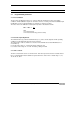
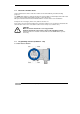
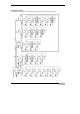
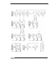
2.3.2 Menu navigation Go through the steps given in the illustrations that follow to get to the required menu.
Operating Instructions DWM 2000 D 7
2.3.3 Summary of programming menus Fct. n° Text Description and settings 1.0.0. 1.1.0. 1.1.1. TEST CHECK ALL MAG. FEQ. 1.1.2. FULL SCALE 1.1.3. U REF 1.1.4. AMPLI 1.1.5. EEP CHECKS 1.1.6. EP CHECKS 1.1.7. ZERO KEY 1.2.0. DIAGNOSTIC Main menu 1.0.0. Sub menu 1.1.0. for check of electronic components Frequency of magnetic field 10 Hz ≤ frequency ≤ 14.5 Hz, operating mode Programmed full scale 1 m/s ≤ full scale ≤ 8 m/s Internal voltage reference U Ref. = 2.
Fct. n° 2.2.0. 2.2.1. 2.2.2. Text CURRENT OUT CURRENT? I 0% 2.2.3. I 100% 2.2.4. TIME CONST. 2.4.0. 2.4.1. SPECIAL LANGUAGE 2.4.2. 2.4.3. PASSWORD EEP PARAM. 2.4.4. FILTER 2.4.5. DISPLAY 2.4.6. DIAMETER Description and settings Sub menu 2.2.0.
2.4 Parameters stored in the EEPROM (menu 2.4.3) Parameter CHECKS 1 CHECKS 2 CHECKS BYTE 1 CHECKS BYTE 2 CPT ALARM. CPT ALARM.2: TEST CORRECTION YES/NO EP CHECKS FS GK U REF T CST TEST AMP FM DIAMETER 10 Comment Check EEPROM n°1 Check EEPROM n°2 Check EEPROM Check EEPROM Counting of all the error messages since the first power-up. Counting of all the error messages since the last reset. Indication of auto diagnostic test level Indication of activation of low velocity linearization.
2.5 Error message list Listed below are the messages which can appear in menu 1.2.2. This function stores all the faults that have occurred since the first connection to power. Error messages MAG. FREQ AMPLI F.S. ZERO KEY EP CHECK EEP CHECK U REF CURR. OUT FS SWIT EEP ZERO Comment Actions No magnetic field frequency out of range 10 Hz ≤ frequency ≤ 14.5 Hz Dysfunction of the amplifier loop Replace the electronics module Programmed full scale out of range (>8 m/s or <1 m/s).
DWM 2000 D nnnnnnnnnnnnnnnnnnnnnnnnnnnnnnnnnnnnnnnnnnn KROHNE measuring technology - Product overview • • • • • • Electromagnetic flowmeters Variable area flowmeters Mass flowmeters Ultrasonic flowmeters Vortex flowmeters • • • • • Level measuring instruments Temperature measuring instruments Pressure measuring instruments Analysis Oil and gas industry Flow controllers Addresses: Germany KROHNE sales companies Northern sales office KROHNE Messtechnik GmbH & Co. KG Bremer Str.