AD_H250_M40_II2GD_R01_en_4002069601_PRT.
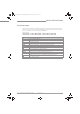
AD_H250_M40_II2GD_R01_en_4002069601_PRT.book Page 2 Friday, July 27, 2012 8:17 AM CONTENTS H250 M40 1 Safety instructions 1.1 1.2 1.3 1.4 3 General notes ................................................................................................................... 3 EC conformity ................................................................................................................... 3 Approval according to the IECEx scheme ................................................................
Safety instructions AD_H250_M40_II2GD_R01_en_4002069601_PRT.book Page 3 Friday, July 27, 2012 8:17 AM SAFETY INSTRUCTIONS 1 H250 M40 1.1 General notes These additional instructions apply to explosion-protected versions of Varaiable area flowmeters with electrical built-ins and the marking II 2 G or II 2 D. They complement the Installation and Operation Instructions for the non-explosion protected versions.
Device description AD_H250_M40_II2GD_R01_en_4002069601_PRT.book Page 4 Friday, July 27, 2012 8:17 AM 2 DEVICE DESCRIPTION H250 M40 2.1 Description of device Variable area flowmeters measure and display the volume flow of flammable and nonflammable gases and liquids. Depending on the device version, electrical limit switch contacts with counter module, reed contacts, a 4...
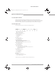
AD_H250_M40_II2GD_R01_en_4002069601_PRT.book Page 5 Friday, July 27, 2012 8:17 AM DEVICE DESCRIPTION 2 H250 M40 2.3 Marking Type designation of the complete unit is shown on the indicator with the rating plate reproduced below (see also description code). Figure 2-1: Example of a rating plate 1 2 3 4 5 6 7 8 9 Device type Manufacturer ATEX & DGRL certification agency code.
AD_H250_M40_II2GD_R01_en_4002069601_PRT.book Page 6 Friday, July 27, 2012 8:17 AM 2 DEVICE DESCRIPTION H250 M40 2.4 Flammable products Atmospheric conditions: An explosive atmosphere is a mixture of air and flammable gases, vapours, mists or dusts under atmospheric conditions. The following values define it Tatm = -20...+60°C / -4...+140°F and Patm = 0.8...1.1 bar. Outside of this range, no key data are available as to ignition behaviour for most mixtures.
AD_H250_M40_II2GD_R01_en_4002069601_PRT.book Page 7 Friday, July 27, 2012 8:17 AM DEVICE DESCRIPTION 2 H250 M40 2.6 Protection types The variable area flowmeter is designed using equipment protection by flameproof enclosures, protection level "Gb" in accordance with EN 60079-1 and equipment dust ignition protection by enclosure, protection level "Db" according to EN 60079-31. The marking is: II 2G Ex d IIC T6 ... T1 Gb or II 2G Ex d IIB T6 ...
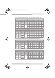
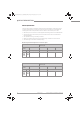
AD_H250_M40_II2GD_R01_en_4002069601_PRT.book Page 8 Friday, July 27, 2012 8:17 AM 2 DEVICE DESCRIPTION H250 M40 2.7 Ambient temperature / temperature classes Due to the influence of the product temperature, variable area flowmeters with built-in electrical equipment (electric variants) are not assigned to any fixed temperature class. In fact, the temperature class of a device is a function of the temperature of both the product and the environment. The classification is outlined in the following tables.
AD_H250_M40_II2GD_R01_en_4002069601_PRT.
AD_H250_M40_II2GD_R01_en_4002069601_PRT.book Page 10 Friday, July 27, 2012 8:17 AM 2 DEVICE DESCRIPTION H250 M40 Reference point observation The permissible product and ambient temperatures may be exceeded or undershot as long as the permissible temperature range of the reference point of the display is not exceeded. The following table contains the permissible maximum values at the reference point. Note: • Reference point is the connection of the equipotential bonding conductor of the M40 indicator.
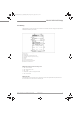
AD_H250_M40_II2GD_R01_en_4002069601_PRT.book Page 11 Friday, July 27, 2012 8:17 AM DEVICE DESCRIPTION 2 H250 M40 2.8 Electrical data Electrical equipment Rated voltage Nominal current Limit switches K1 / K2 OC Output 10 - 30 VDC ≤100 mA Limit switches K1 / K2 NAMUR Output 5- 25 VDC ≤1 / ≥3 mA Reed contacts R1 / R2 0 - 32 VDC ≤100 mA Signal output ESK4 14 - 32 VDC 4...20mA with HART® communication Switching output ESK4-T OC output 8 - 32 VDC 1...
Installation AD_H250_M40_II2GD_R01_en_4002069601_PRT.book Page 12 Friday, July 27, 2012 8:17 AM 3 INSTALLATION H250 M40 3.1 Installation Installation and setup must be carried out according to the applicable installation installation standards (e.g. EN 60079-14) by qualified personnel trained in explosion protection. The information given in the Installation and Operation Instructions and the Supplementary Installation and Operation Instructions must always be observed.
AD_H250_M40_II2GD_R01_en_4002069601_PRT.book Page 13 Friday, July 27, 2012 8:17 AM INSTALLATION 3 H250 M40 3.2 Special conditions Equipotential bonding Variable area flowmeters must be included in the equipotential bonding of the hazardous area. Electronics compartment lock Lock the dustproof and/or flameproof electronics compartment of the variable area flowmeter during operation. First tighten the cover by hand. Then tighten the cover again by about 90°.
Electrical connections AD_H250_M40_II2GD_R01_en_4002069601_PRT.book Page 14 Friday, July 27, 2012 8:17 AM 4 ELECTRICAL CONNECTIONS H250 M40 4.1 General notes Rated values for insulation • The insulation of the H.../..../M40 - Ex variable area flowmeter is rated in compliance with IEC 60 664-1.
AD_H250_M40_II2GD_R01_en_4002069601_PRT.book Page 15 Friday, July 27, 2012 8:17 AM ELECTRICAL CONNECTIONS 4 H250 M40 CAUTION! The IP protection category of the signal converter housing is largely determined by the cable gland used and the installation. 4.2 Power supply The variable area flowmeter does not require a separate power supply. The required supply for the built-in electronics is provided via the 4...20mA current output and the bus connection. 4.
AD_H250_M40_II2GD_R01_en_4002069601_PRT.book Page 16 Friday, July 27, 2012 8:17 AM 4 ELECTRICAL CONNECTIONS H250 M40 4.4 Grounding and equipotential bonding The signal converter shall be connected to the equipotential bonding system of the hazardous area via the internal or external grounding connection on the signal converter housing. The measuring unit and the signal converter are electrically connected via an equipotential bonding connection.
Operation AD_H250_M40_II2GD_R01_en_4002069601_PRT.book Page 17 Friday, July 27, 2012 8:17 AM OPERATION 5 H250 M40 5.1 Start up Start-up is only permitted when the variable area flowmeter: • is correctly installed in the system and connected. • has been checked for the proper state with regard to its installation and connection requirements. • and the electronics compartment have been properly closed (pressure-resistant casing or dustproof housing) and the applicable special lock has been fitted.
Service AD_H250_M40_II2GD_R01_en_4002069601_PRT.book Page 18 Friday, July 27, 2012 8:17 AM 6 SERVICE H250 M40 6.1 Maintenance Maintenance work of a safety-relevant nature within the meaning of explosion protection may only be carried out by the manufacturer, his authorised representative or under the supervision of authorised inspectors. To maintain proper condition, regular inspections are required for systems in hazardous areas.
AD_H250_M40_II2GD_R01_en_4002069601_PRT.book Page 19 Friday, July 27, 2012 8:17 AM SERVICE 6 H250 M40 Exchanging the entire device Observe the information above. Also, ensure that all process connections and the pipeline are depressurized and free of product. Where environmentally critical products are concerned, carefully decontaminate the wetted parts of the flange system after dismantling. WARNING! • Pressurized pipes have to be depressurized before removing the measuring unit.
AD_H250_M40_II2GD_R01_en_4002069601_PRT.book Page 20 Friday, July 27, 2012 8:17 AM © KROHNE 07/2012 - 4002069601 - MA H250/M40-Ex-II2GD-AD R01 en - Subject to change without notice.