Operating Instructions OPTISWITCH 5200 C, 5250 C with contactless electronic switch
Contents Contents 1 About this document 1.1 1.2 1.3 2 . . . . . . . . . . . . . . . . . . . . . . . . . . . . . . . . . . . . . . . . . . .. .. .. .. .. .. 5 5 5 5 6 6 Configuration. . . . . . . Principle of operation . Operation . . . . . . . . . Storage and transport . . . . . . . . . . . . . . . . . . . . . . . . . . . . . . . . . . . . . . . . . . . . . . . . . . . . .. .. .. .. 7 7 9 9 . . . . . . . . . . . . . . . . General instructions. . . . . . . . . . . . . . . . .
Contents 9 Supplement Technical data. . . . . . . . . . . . . . . . . . . . . . . . . 26 Dimensions . . . . . . . . . . . . . . . . . . . . . . . . . . . 31 30433-EN-060831 9.1 9.
About this document 1 About this document 1.1 Function This operating instructions manual has all the information you need for quick setup and safe operation. Please read this manual before you start setup. 1.2 Target group This operating instructions manual is directed to trained, qualified personnel. The contents of this manual should be made available to these personnel and put into practice by them. 1.3 Symbolism used Information, tip, note This symbol indicates helpful additional information.
For your safety 2 For your safety 2.1 Authorised personnel All operations described in this operating instructions manual must be carried out only by trained specialist personnel authorised by the operator. For safety and warranty reasons, any internal work on the instruments must be carried out only by personnel authorised by the manufacturer. 2.2 Appropriate use OPTISWITCH 5200 C, 5250 C is a sensor for level detection.
For your safety 2.6 SIL conformity OPTISWITCH 5200 C, 5250 C fulfills the requirements of functional safety according to IEC 61508/IEC 61511. You can find further information in the supplementary instructions manual "Safety Manual - Functional safety (SIL) OPTISWITCH 5XXX". 2.7 Safety instructions for Ex areas Please note the Ex-specific safety information for installation and operation in Ex areas.
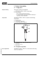
Product description 3 Product description 3.1 Configuration Scope of delivery The scope of delivery encompasses: l l Components OPTISWITCH 5200 C, 5250 C level sensor Documentation - this operating instructions manual - Ex specific safety instructions (with Ex versions), if necessary further certificates OPTISWITCH 5200 C, 5250 C consists of the following components: l l l Housing cover Housing with electronics process fitting with tuning fork 1 2 3 Fig.
Product description It is designed for industrial use in all areas of process technology and can be used in liquids. Typical applications are overfill and dry run protection. With a tuning fork of only 40 mm length, OPTISWITCH 5200 C, 5250 C can be also mounted, e.g. in pipelines from DN 25. The small tuning fork allows use in vessels, tanks and pipes. Thanks to its simple and robust measuring system, OPTISWITCH 5200 C, 5250 C is virtually unaffected by the chemical and physical properties of the liquid.
Product description 3.3 Operation The switching condition of OPTISWITCH 5200 C, 5250 C with plastic housing can be checked when the housing is closed (signal lamp). With the basic setting, products with a density >0.7 g/cm³ (>0.025 lbs/in³) can be detected. The instrument can be adapted if products with lower density should be measured.
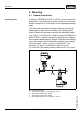
Mounting 4 Mounting 4.1 General instructions Switching point In general, OPTISWITCH 5200 C, 5250 C can be mounted in any position. The instrument must be mounted in such a way that the tuning fork is at the height of the requested switching point. The tuning fork has lateral markings (notches), marking the switching point with vertical mounting. The switching point refers to water with the basic setting of the sensitivity switch >=0.7 g/cm³ (>=0.025 lbs/in³).
Mounting 1 Fig. 3: Horizontal mounting 1 Switching point 2 1 Fig. 4: Horizontal mounting (recommended installation location - particularly for adhesive products) 1 Switching point 2 Marking with screwed version on top - with flange versions directed to the flange holes With flange versions, the fork is directed to the flange holes in the following way. Fig.
Mounting condensation water can thus drain off. This applies mainly to mounting outdoors, in areas where moisture is expected (e.g. by cleaning processes) or on cooled or heated vessels. Fig. 6: Measures against moisture penetration Transport Do not hold OPTISWITCH 5200 C, 5250 C on the tuning fork. Particularly with flange or tube versions, the tuning fork can be damaged by the instrument weight. Transport coated instruments very carefully and avoid touching the tuning fork.
Mounting 4.2 Mounting instructions Welded socket OPTISWITCH 5200 C, 5250 C has a defined thread starting point. This means that every OPTISWITCH 5200 C, 5250 C is in the same fork position after being screwed in. Remove therefore the supplied seal from the thread of OPTISWITCH 5200 C, 5250 C. This seal is not required when using a welded socket with O-ring in front. Keep in mind that this welded socket is not suitable for coated instrument versions.
Mounting When used in adhesive and viscous products, the tuning fork should protrude into the vessel to avoid buildup. For that reason, sockets for flanges and mounting bosses should be avoided when mounting horizontally. Inflowing medium If OPTISWITCH 5200 C, 5250 C is mounted in the filling stream, unwanted switching signals may be generated. Mount OPTISWITCH 5200 C, 5250 C at a location in the vessel where no disturbing influence from e.g. filling openings, agitators etc. can occur.
Mounting a longer tube version be necessary, you can provide a suitable support or guy directly above the tuning fork to secure the extension tube. This measure applies particularly to applications in Ex areas category 1G or WHG. Make sure that the tube is not bent by this measure. 30433-EN-060831 Fig.
Connecting to voltage supply 5 Connecting to voltage supply 5.1 Preparing the connection Note safety instructions Generally not the following safety instructions: l Connect only in the complete absence of line voltage Take note of safety instructions for Ex applications In hazardous areas you should take note of the appropriate regulations, conformity and type approval certificates of the sensors and power supply units. Select power supply Connect the power supply according to the following diagrams.
Connecting to voltage supply 1 Unscrew the housing cover 2 Loosen compression nut of the cable entry 3 Remove approx. 10 cm (4 in) of the cable mantle, strip approx. 1 cm (0.
Connecting to voltage supply Electronics and connection compartment SW E60C 20-253V AC/DC 1 2 max 400mA +L + N L N A B 1 12 0,5 g / cm3 0,7 g / cm3 2 3 1 2 5 Fig.
Connecting to voltage supply 1 2 AC L1 N DC + - + 30433-EN-060831 Fig.
Set up 6 Set up 6.1 General The numbers in brackets refer to the following illustrations. Function/Configuration The switching condition of the electronics can be checked on the plastic housing with closed housing cover (control lamp). In the basic setting, products with a density >0.7 g/cm³ (>0.025 lbs/in³) can be detected. For products with lower density, the switch must be set to >0.5 g/cm³ (>0.018 lbs/in³).
Set up Signal lamp (1) Control lamp (LED) for indication of the switching condition l l l green = output conducts red = output blocks red (flashing) = failure Mode adjustment (2) With the mode adjustment (A/B) you can change the switching condition of the relay. You can set the required mode acc. to the "Function chart" (A - max. detection or overfill protection, B - min. detection or dry run protection).
Set up Level Failure of the supply voltage (mode A/B) Switching status Control lamp any 1 2 Switch open Failure any 1 2 Switch open flashes red 30433-EN-060831 22 OPTISWITCH 5200 C, 5250 C - with contactless electronic switch
Maintenance and fault rectification 7 Maintenance and fault rectification 7.1 Maintenance When used as directed in normal operation, OPTISWITCH 5200 C, 5250 C is completely maintenance free. 7.2 Rectify faults Causes of malfunction OPTISWITCH 5200 C, 5250 C offers maximum reliability. Nevertheless faults can occur during operation. These may be caused by the following, e.g.
Maintenance and fault rectification l Wrong mode selected à Set the correct mode on the mode switch (max.: overfill protection; min.: dry run protection). Wiring should be carried out according to the quiescent current principle. ? Signal lamp flashes red l Electronics has detected a failure à Exchange instrument or return instrument for repair ? The signal lamp flashes alternately red and green l instrument defective à Exchange instrument or return instrument for repair 7.
Dismounting 8 Dismounting 8.1 Dismounting procedure Warning: Before dismounting, be aware of dangerous process conditions such as e.g. pressure in the vessel, high temperatures, corrosive or toxic products etc. Take note of chapters "Mounting" and "Connecting to power supply" and carry out the listed steps in reverse order. With Ex instruments, the housing cover may only be opened if there is no explosive atmosphere present. 8.
Supplement 9 Supplement 9.1 Technical data General data Material 316L corresponds to 1.4404 or 1.4435 Materials, wetted parts - Process fitting - thread 316L, Hastelloy C4 (2.4602) - Process fitting - flange 316L, 316L with Hastelloy C4 plated, 316L with ECTFE coated, 316L with PFA coated - Process seal Klingersil C-4400 - Tuning fork 316L, Hastelloy C4 (2.4610) - Extension tube ø 21.3 mm (0.84 in) 316L, Hastelloy C4 (2.
Supplement Surface quality - Standard Ra approx. 3 µm (approx. 1.18-4 in) - Ra <0.8 µm (<3.
Supplement OPTISWITCH 5200 C, 5250 C of 316L/ Hastelloy C4 (2.
Supplement Electromechanical data Cable entry/plug (dependent on the version) - Single chamber housing l or: l 1x cable entry M20x1.5 (cable-ø 5 … 9 mm), 1x blind stopper M20x1.5, attached 1x cable entry M20x1.5 1x cable entry ½ NPT, 1x blind stopper ½ NPT, 1x cable entry ½ NPT or: l Screw terminals 1x plug M12x1, 1x blind stopper M20x1.5 for wire cross-section up to 1.5 mm² (0.0023 in²) Adjustment elements Mode switch - A Max. detection or overflow/overfill protection - Min.
Supplement Overfill protection acc.
Supplement 9.2 Dimensions OPTISWITCH 5200 C, 5250 C ~ 69mm (2 23/32") 1 2 M20x1,5 3 15: Housing versions Plastic housing Stainless steel housing Aluminium housing 30433-EN-060831 Fig.
Supplement 2 L 34mm (1 11/32") 19mm (3/4") 50mm (1 31/32") ø33,7mm (1 21/64") 32 6 5 16: OPTISWITCH 5200 C, 5250 C, threaded version Thread Tri-Clamp Cone DN 25 Bolting DN 40 Flange Gas-tight leadthrough Temperature adapter = Sensor length, see "Technical data" OPTISWITCH 5200 C, 5250 C - with contactless electronic switch 30433-EN-060831 Fig.
30433-EN-060831 Supplement OPTISWITCH 5200 C, 5250 C - with contactless electronic switch 33
Supplement 30433-EN-060831 34 OPTISWITCH 5200 C, 5250 C - with contactless electronic switch
30433-EN-060831 Supplement OPTISWITCH 5200 C, 5250 C - with contactless electronic switch 35
Subject to change without notice 30433-EN-060831