
Data Sheet


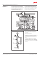
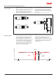


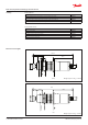


Table Of Contents

Product concept/
applications
To control if a liquid level is within predened
allowed limits, two LLS 4000 are installed in an
upper and a lower limit position respectively. By
this setup the liquid level is between the two
level switches and the lower switch will sense
liquid, while the upper will sense gas.
In case the liquid level moves outside the limits,
one of the switches will sense opposite and
switch the built-in relay. This relay switch function
should be used for alarm settings. This is made
easy when connected to the system PLC.
Upper
LLS 4000/U
Lower
LLS 4000/U
Liq. Level
The LLS can be used wherever liquid levels of
ammonia and certain H(C)FC refrigerants must
be controlled.
The LLS comes in 2 versions:
- A standard version, which is applicable for most
refrigeration or processing plants, and is fully
configurable regarding type of liquid and relay
setting.
- A SIL2 version applicable for SIL compliant
process plants. This version is non-configurable
regarding relay setting (see section: Configurable
parameters) and is intended specific as the upper
level switch.
SVA
QDV
15
BSV
ICF 25-6-5A
EKE
347
AKS 4100
LLG
BSV
SNV
SNV
SVA
SVA
LLG
SNV
SVA
SFA
+DSV
SVA
LLS 4000
SVA
SVA
SCA-X
RT
260A
RT
260A
SNV
SNV
SVA
SVA
SNV
SNV
SNV
SCA-X
FIA
FIA
LLS 4000
Data sheet | Liquid Level Switch, type LLS 4000/4000U
AI323832972563en-000101 | 3
© Danfoss | DCS (ms) | 2020.02