MANUALE DI INSTALLAZIONE - INSTALLATION MANUAL PIATTAFORME INTEGRATE - INTEGRATED PLATFORMS KSI1000016.300 - KSI1100016.300 - KSI1000048.300 - KSI1100048.300 - KSI1100128.
INDEX Introduction............................................................................................................................................................. 17 Specification for model.......................................................................................................................................... 18 Devices features.....................................................................................................................................................
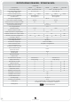
SPECIFICATIONS FOR MODEL - TECHNICAL DATA HARDWARE Control Panel lares 16 lares 16-IP lares 48-IP lares 128-IP Power supply voltage 230 V~ -15/+10% 50 Hz 0,3A 230 V~ -15/+10% 50 Hz 0,5A Power Supply Battery Charger (Type A norm EN50131-6) 14,1V ± 1% 1,7A 14,1V ± 1% 3,5A Current consumption (max.) Maximum current available for external devices 60mA 100mA 60mA 100mA 600 mA grade 2 100 mA grade 3 Max. output voltage ripple 1400 mA grade 2 200 mA grade 3 Max.
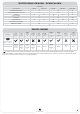
SPECIFICATIONS FOR MODEL - TECHNICAL DATA SOFTWARE Control Panel lares 16 lares 16-IP lares 48 lares 48-IP lares 128-IP Manageable partitions 8 12 20 Programmable switch-on modes 16 32 64 Timers 16 16 16 Daily scheduler 32 32 SI User codes 16 Transponder keys 64 48 64 128 64 Recorded events (logger) 128 128 1500 Telephone numbers 20 50 100 DEVICES FEATURES DEVICE auxi expansion module ergo LCD keypad imago outdoor siren on BUS radius indoor siren on BUS volo pr
LOGICAL FEATURES ZONE / INPUTS Every board of the system carries 6 programmable inputs and 4 terminals which, upon installation, can be configured as inputs or as outputs (essentially we have up to 10 inputs on the system). Moreover, a specific connector is available for connecting the protections against opening and removal of the control panel from the wall. Depending on the model, the number of inputs can be extended up to a maximum of 128.
PARTITIONS Each input can be associated freely to a group (partition) in order to simplify its management. There are 8, 12 or 20 partitions available, depending on the model (see Table). For every partition, it is possible to program the entry, exit, warning and patrol times and to define a variety of switch-on and triggering methods. OUTPUTS The control panel PC board carries one supervised double-switching programmable 1A relay output and four 500mA OC outputs.
ETHERNET CONNECTIVITY - LAN NETWORK The Ethernet interface is already integrated in the PC board of the lares 16-IP, lares 48-IP and lares 128-IP versions: this solution allows managing the system easily via any internet connection from anywhere around the world. ETHERNET ETHERNET Network Link It’s a link between the PC and the system. Using basis SW you can configure the system, update vocal messages, the FW of the main board and the peripherals, read the real time of the zone and partitions.
MONITORING THE POWER SUPPLY lares monitors both the external power supply voltage and the battery. It periodically checks the efficiency status of the battery, and will issue a warning in the case of problems. Moreover, in case of prolonged absence of power supply, the system turns the battery off to prevent deep discharges.
lares AND HOME AUTOMATIONS The lares control panel is unique in this concern, too. Its own platform integrates itself with extreme ease in any Home Integration & Automation logics. It takes an absolutely leading role, as it is perfectly capable of managing autonomously the domotic applications you always dreamt of for your house – without any help from a PC or the use of any complicated programs.
PARTS IDENTIFICATION hereafter, shows the main parts composing the lares system. The picture also shows the power supply connections in detail: pay attention to the earth connection. The two holes on the case bottom provide an wide passage of cables for wiring the peripheral devices also in the case of quite large systems.
1. Metal bottom 2. Large holes for passing cables 3. Bottom securing holes 4. System’s board brackets 5. auxi PC board brackets 6. Anti-tamper micro-switch 7. Micro-switch cable + connector 8. Earth connections on threaded pin and nut 9. Control panel board 10. Control panel micro-controller 11. Interconnection terminals 12. Programming USB connector 13. USB key (optional) 14. Power supply cable 15. 12V battery 16. Switching power supply unit 17. Battery terminals 18. Power supply unit terminals 19.
CONNECTIONS The lares control panel is governed by a powerful 32-bit micro-controller that controls all of its functions. Figure 2 below shows – in addition to an overall view of the PC board and the use of the various jumpers – the layout of the system’s terminals and provides a short description of their use. AL - 12V battery connector AL T STOP TAMP, T - Tamper Open: Tamper reveal ON Closed: Tamper reveal OFF STOP - Factory Data 1. Turn the control panel off 2. Remove the STOP jumper 3.
TYPICAL CONNECTION DIAGRAM A basic connection diagram is shown in figure.
KS-BUS CONNECTION DIAGRAM (RS485) Peripheral units of the Ksenia system are connected through the fast KS-BUS. It is recommended not to exceed, for each wiring branch (e.g. control panel - device), the maximum length of 500 m (1400 feet), and the complete wiring should not be longer than 1000 m (2800 feet). Always use a screened cable with one end of the screen connected to the control panel’s ground6 and the other end free. Figure below is an example.
Installation of these systems must be carried out strictly in accordance with the instructions described in this manual, and in compliance with the local laws and bylaws in force.. lares series have been designed and made with the highest standards of quality and performance adopted by Ksenia Security. Is recommended that the installed system should be completely tested at least once a month. Test procedures depends on the system configuration. Ask to the installer for the procedures to be followed.
lares installation manual 16
ENVIROMENTAL CARE lares™ is designed and manufactured with the following features to reduce its environmental impact: 1. Halogen-free laminates and lead-free PCBA 2. Low current consumption 3. Packaging made mostly of recycled fibres and materials obtained from renewable sources www.kseniasecurity.com RMX0300005.