
Installation Instructions


10
lares
installation manual
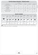
PARTS IDENTIFICATION
hereafter, shows the main parts composing the lares system. The picture also shows the power supply
connections in detail: pay attention to the earth connection. The two holes on the case bottom provide an
wide passage of cables for wiring the peripheral devices also in the case of quite large systems.
+P1 M1 M2 - +P1 M3 M4 -
NC C NO +A +R
+P i1 i2 - - - - -+P +Pi3 i4 i5 i6 A B+ 12V
CENTRALE - CONTROL PANEL
CENTRALE - ZENTRALE
4
1
55
5
6
67
9
8
10
11
11
13
14
15
16
17 17
19
19
19 19
20
21
12
54
4
4
2
2
2
33
33