ENR Series Network Video Recorder User Manual
User Manual of Network Video Recorder About this Manual This Manual is applicable to Network Video Recorder (NVR). The Manual includes instructions for using and managing the product. Pictures, charts, images and all other information hereinafter are for description and explanation only. The information contained in the Manual is subject to change, without notice, due to firmware updates or other reasons.
User Manual of Network Video Recorder Regulatory Information FCC Information FCC compliance: This equipment has been tested and found to comply with the limits for a digital device, pursuant to part 15 of the FCC Rules. These limits are designed to provide reasonable protection against harmful interference when the equipment is operated in a commercial environment.
User Manual of Network Video Recorder Safety Instruction These instructions are intended to ensure that user can use the product correctly to avoid danger or property loss. The precaution measure is divided into “Warnings” and “Cautions” Warnings: Serious injury or death may occur if any of the warnings are neglected. Cautions: Injury or equipment damage may occur if any of the cautions are neglected.
User Manual of Network Video Recorder Preventive and Cautionary Tips Before connecting and operating your device, please be advised of the following tips: • • • • • Ensure unit is installed in a well-ventilated, dust-free environment. Unit is designed for indoor use only. Keep all liquids away from the device. Ensure environmental conditions meet factory specifications. Ensure unit is properly secured to a rack or shelf.
User Manual of Network Video Recorder Thank you for purchasing our product. If there is any question or request, please do not hesitate to contact dealer. The figures in the manual are for reference only.
User Manual of Network Video Recorder Product Key Features General l Connectable to network cameras, network dome and encoders. l Connectable to the third-party network cameras like ACTI, Arecont, AXIS, Bosch, Brickcom, Canon, PANASONIC, Pelco, SAMSUNG, SANYO, SONY, Vivotek and ZAVIO, and cameras that adopt ONVIF or PSIA protocol. l Connectable to the smart IP cameras. l PAL/NTSC adaptive video inputs. l Each channel supports dual-stream. l Up to 16 network cameras can be connected.
User Manual of Network Video Recorder l Local redundant recording. l Provide new playback interface with easy and flexible operation. l Searching and playing back record files by camera No., recording type, start time, end time, etc. l Smart search for the selected area in the video. l Zooming in when playback. l Reverse playback of multi-channel. l Supports pause, play reverse, speed up, speed down, skip forward, and skip backward when playback, and locating by dragging the mouse.
User Manual of Network Video Recorder l Remote viewing of the device status, system logs and alarm status. l Remote keyboard operation. l Remote locking and unlocking of control panel and mouse. l Remote HDD formatting and program upgrading. l Remote system restart and shutdown. l Alarm and exception information can be sent to the remote host l Remotely start/stop recording. l Remotely start/stop alarm output. l Remote JPEG capture. l Two-way audio and voice broadcasting. l Embedded WEB server.
User Manual of Network Video Recorder TABLE OF CONTENTS Product Key Features ................................................................................................................................6 Chapter 1 Introduction ..........................................................................................................................13 1.1 Front Panel .......................................................................................................................................
User Manual of Network Video Recorder 5.1 Configuring Parameters ...................................................................................................................62 5.2 Configuring Recording Schedule ....................................................................................................65 5.3 Configuring Motion Detection Recording .......................................................................................68 5.4 Configuring Alarm Triggered Recording ........
User Manual of Network Video Recorder 9.7 People Gathering Detection ...........................................................................................................124 9.8 Fast Moving Detection ..................................................................................................................124 9.9 Parking Detection ..........................................................................................................................125 9.
User Manual of Network Video Recorder 12.7 Configuring HDD Error Alarms ....................................................................................................171 Chapter 13 Camera Settings..................................................................................................................172 13.1 Configuring OSD Settings .............................................................................................................173 13.2 Configuring Privacy Mask.................
User Manual of Network Video Recorder Chapter 1 Introduction 13
User Manual of Network Video Recorder 1.1 Front Panel Figure 1. 1 Front Panel Table 1. 1 Description of Control Panel Buttons No. 1 Name Function Description POWER POWER indicator turns green when DVR is powered up. STATUS STATUS indicator lights in red when data is being read from or written to HDD. Tx/Rx Tx/Rx indictor blinks green when network connection is functioning properly. The DIRECTION buttons are used to navigate between different fields and items in menus.
User Manual of Network Video Recorder 1.2 IR Remote Control Operations The NVR may also be controlled with the included IR remote control, shown in Figure 1. 2. Batteries (2×AAA) must be installed before operation. Figure 1. 2 Remote Control The keys on the remote control closely resemble the ones on the front panel. Table 1. 2 Description of the Soft Keyboard Icons No. Name Description 1 POWER Power on/off the device. 2 DEV Enables/Disables Remote Control.
User Manual of Network Video Recorder No. Name Description On checkbox fields, pressing the button will check the checkbox. In PTZ Control mode, the button adjusts the iris of the camera. In Playback mode, it can be used to generate video clips for backup. Enter/exit the folder of USB device. 5 A Button Adjust focus in the PTZ Control menu. It is also used to switch between input methods (upper and lowercase alphabet, symbols and numeric input). 6 REC Button Enter the Manual Record setting menu.
User Manual of Network Video Recorder No. Name Description In Playback mode, it is used to switch between play and reverse play. 17 PTZ Control Buttons Buttons to adjust the iris, focus and zoom of a PTZ camera. 18 F2 Button Cycle through tab pages. In synchronous playback mode, it is used to switch between channels. Troubleshooting Remote Control: Make sure you have installed batteries properly in the remote control. And you have to aim the remote control at the IR receiver in the front panel.
User Manual of Network Video Recorder 1.2 USB Mouse Operation A regular 3-button (Left/Right/Scroll-wheel) USB mouse can also be used with this NVR. To use a USB mouse: 1. Plug USB mouse into one of the USB interfaces on the front panel of the NVR. 2. The mouse should automatically be detected. If in a rare case that the mouse is not detected, the possible reason may be that the two devices are not compatible, please refer to the recommended the device list from your provider.
User Manual of Network Video Recorder 1.3 Input Method Description Figure 1. 1 Soft Keyboard (1) Figure 1. 2 Soft Keyboard (2) Description of the buttons on the soft keyboard: Table 1.
User Manual of Network Video Recorder 1.4 Rear Panel The rear panel vaires according to different models. Real Panel without POE Interface Figure 1. 3 Real Panel without POE Interface Table 1. 5 Description of Rear Panel Interfaces No. Item Description 1 Power Supply DC 12V power supply. 2 Audio In RCA connector for audio input. 3 HDMITM Interface HDMITM video output connector.
User Manual of Network Video Recorder The 16-ch devices have both 8 and 16 independent 100 Mbps PoE network interfaces models. Table 1. 6 Description of Rear Panel Interfaces No. Item Description 1 Power Supply DC 48V power supply for 4-ch device and AC 100~240V for 8-ch and 2 Audio In 3 HDMI TM 4 LAN Network Interface 10 /100 /1000 Mbps self-adaptive Ethernet interface 5 Audio Out RCA connector for audio output. 6 VGA Interface DB9 connector for VGA output.
User Manual of Network Video Recorder Chapter 2 Getting Started 22
User Manual of Network Video Recorder 2.1 Starting Up and Shutting Down the NVR Purpose: Proper startup and shutdown procedures are crucial to expanding the life of the NVR. Before you start: Check that the voltage of the extra power supply is the same with the NVR’s requirement, and the ground connection is working properly. Starting up the NVR: Steps: 1. Check the power supply is plugged into an electrical outlet.
User Manual of Network Video Recorder 1. Enter the Shutdown menu by clicking Menu > Shutdown. 2. Click the Logout button to lock the NVR or the Reboot button to reboot the NVR.
User Manual of Network Video Recorder 2.2 Setting Admin Password Purpose: For the first-time access, you need to activate the device by setting an admin password. No operation is allowed before activation. Steps: 1. Input the same password in the text field of Create New Password and Confirm New Password. Figure 2.
User Manual of Network Video Recorder 2.3 Using the Wizard for Basic Configuration Purpose: After admin password is set, the setup wizard pops up automatically. It can walk you through some basic settings of the NVR. Figure 2. 5 Start Wizard Interface Steps: 1. If you don’t want to use the setup wizard at that moment, click the Exit button. You can also choose to use the Setup Wizard next time by leaving the “Start wizard when the device starts?” checkbox checked. 2.
User Manual of Network Video Recorder Figure 2. 7 Network Configuration for Models with POE Interface For the models have the PoE the internal NIC IPv4 address should be configured for the cameras connecting to the PoE or built-in switch network interface of the NVR. 4. Click Next button after you configured the basic network parameters. Then you will enter the Cloud P2P interface. Configure the Cloud P2P according to your need. Figure 2. 8 Advanced Network Parameters 5.
User Manual of Network Video Recorder Figure 2. 9 Advanced Network Parameters 6. After configuration finishes, click Next button to enter HDD Management interface. Figure 2. 10 HDD Management 7. To initialize the HDD, click the Init button. Initialization removes all the data saved in the HDD. 8. Click Next button to enter the IP Camera Management interface. 9. Click Search to search the online IP Camera and the Security status shows whether it is active or inactive.
User Manual of Network Video Recorder Figure 2. 11 IP Camera Management 10. Click Next button. Configure the recording for the searched IP Cameras. Figure 2. 12 Record Settings 11. Click OK to complete the startup Setup Wizard.
User Manual of Network Video Recorder 2.4 Login and Logout 2.4.1 User Login Purpose: If NVR has logged out, you must login the device before operating the menu and other functions. Steps: 1. Select the User Name in the dropdown list. Figure 2. 13 Login Interface 2. Input Password. 3. Click OK to log in. The device gets locked for 60 seconds if the admin user performs 7 failed password attempts (5 attempts for the guest/operator). Figure 2. 14 User Account Protection 2.4.
User Manual of Network Video Recorder Figure 2. 15 Logout 2. Click Logout. After you have logged out the system, menu operation on the screen is invalid. It is required to input a user name and password to unlock the system.
User Manual of Network Video Recorder 2.5 Adding and Connecting the IP Cameras 2.5.1 Activating the IP Camera Purpose: Before adding the camera, make sure the IP camera to be added is in active status. Steps: 1. Select the Add IP Camera option from the right-click menu in live view mode or click Menu> Camera> Camera to enter the IP camera management interface. For the IP camera detected online in the same network segment, the Security status shows whether it is active or inactive. Figure 2.
User Manual of Network Video Recorder admin password of the operating NVR. Figure 2. 18 Set New Password Create New Password: If the admin password is not used, you must create the new password for the camera and confirm it. STRONG PASSWORD RECOMMENDED– We highly recommend you create a strong password of your own choosing (using a minimum of 8 characters, including upper case letters, lower case letters, numbers, and special characters) in order to increase the security of your product.
User Manual of Network Video Recorder Figure 2. 19 Quick Adding IP Camera Interface 3. Select the detected IP camera and click the Add button to add it directly, and you can click the Search button to refresh the online IP camera manually. Or you can choose to custom add the IP camera by editing the parameters in the corresponding textfiled and then click the Add button to add it. OPTION 2: Steps: 1.
User Manual of Network Video Recorder 4. (For the encoders with multiple channels only) check the checkbox of Channel Port in the pop-up window, as shown in the following figure, and click OK to add multiple channels. Figure 2. 21 Selecting Multiple Channels OPTION 3: Steps: 1) On the IP Camera Management interface, click the Custom Adding button to pop up the Add IP Camera (Custom) interface. Figure 2.
User Manual of Network Video Recorder strong password, weak password and risk password. Figure 2. 23 Successfully Added IP Cameras Table 2. 1 Explanation of the icons Icon Explanation Icon Edit basic parameters of the camera Explanation Add the detected IP camera. The camera is disconnected; you can Delete the IP camera click the icon to get the exception information of camera. Play the live video of the connected Advanced settings of the camera. camera.
User Manual of Network Video Recorder Figure 2. 24 Edit the Parameters Channel Port: If the connected device is an encoding device with multiple channels, you can choose the channel to connect by selecting the channel port No. in the dropdown list. 2. Click OK to save the settings and exit the editing interface. To edit advanced parameters: 1. Drag the horizontal scroll bar to the right side and click the icon. Figure 2. 25 Network Configuration of the Camera 2.
User Manual of Network Video Recorder Figure 2. 26 Password Configuration of the Camera 3. Click OK to save the settings and exit the interface. Configuring the customized protocols Purpose: To connect the network cameras which are not configured with the standard protocols, you can configure the customized protocols for them. Steps: 1. Click the Protocol button in the custom adding IP camera interface to enter the protocol management interface. Figure 2.
User Manual of Network Video Recorder Example: rtsp://192.168.1.55:554/ch1/main/av_stream. Protocol Name: Edit the name for the custom protocol. Enable Substream: If the network camera does not support sub-stream or the sub-stream is not needed leave the checkbox empty. Type: The network camera adopting custom protocol must support getting stream through standard RTSP. Transfer Protocol: Select the transfer protocol for the custom protocol. Port: Set the port No. for the custom protocol.
User Manual of Network Video Recorder Steps: 1. Enter the Camera Management interface. Menu> Camera> Camera Figure 2. 29 List of Connected Cameras The cameras connecting to the PoE interface cannot be deleted in this menu. 2. Click the • button, and select the Adding Method in the drop-down list. Plug-and-Play: It means that the camera is connected to the PoE interface, so in this case, the parameters of the camera can’t be edited.
User Manual of Network Video Recorder camera. Figure 2.
User Manual of Network Video Recorder Chapter 3 Live View 42
User Manual of Network Video Recorder 3.1 Introduction of Live View Live view shows you the video image getting from each camera in real time. The NVR automatically enters Live View mode when powered on. It is also at the very top of the menu hierarchy, thus pressing the ESC many times (depending on which menu you’re on) brings you to the Live View mode.
User Manual of Network Video Recorder 3.2 Operations in Live View Mode In live view mode, there are many functions provided. The functions are listed below. • • • Single Screen: showing only one screen on the monitor. Multi-screen: showing multiple screens on the monitor simultaneously. Auto-switch: the screen is auto switched to the next one. And you must set the dwell time for each screen on the configuration menu before enabling the auto-switch. Menu > Configuration > Live View > Dwell Time.
User Manual of Network Video Recorder Figure 3. 1 Right-click Menu The right-click menu varies according to different models, please refer to the actual GUI menu of the device. 3.2.2 Quick Setting Toolbar in Live View Mode On the screen of each channel, there is a quick setting toolbar which shows when you single click the mouse in the corresponding screen. Figure 3. 2 Quick Setting Toolbar Table 3.
User Manual of Network Video Recorder Figure 3. 3 Digital Zoom Image Settings icon can be selected to enter the Image Settings menu. Figure 3. 4 Image Settings- Preset You can set the image parameters like brightness, contrast, saturation and hue. Figure 3.
User Manual of Network Video Recorder Live View Strategy can be selected to set strategy, including Real-time, Balanced, Fluency. Figure 3.
User Manual of Network Video Recorder 3.3 Adjusting Live View Settings Purpose: Live View settings can be customized according to different needs. You can configure the output interface, dwell time for screen to be shown, mute or turning on the audio, the screen number for each channel, etc. Steps: 1. Enter the Live View Settings interface. Menu > Configuration > Live View Figure 3.
User Manual of Network Video Recorder 1) 2) . Select a View mode in Select the small window, and double-click on the channel number to display the channel on the window. If you do not want the camera to be displayed on the live view interface, click the corresponding to stop it. You can also click button to start live view for all the channels and click to stop all the live view. 3) Click the Apply button to save the setting. 3.
User Manual of Network Video Recorder Chapter 4 PTZ Controls 50
User Manual of Network Video Recorder 4.1 Configuring PTZ Settings Purpose: Follow the procedure to set the parameters for PTZ. The configuring of the PTZ parameters should be done before you control the PTZ camera. Steps: 1. Enter the PTZ Settings interface. Menu > Camera > PTZ Figure 4. 1 PTZ Settings 2. Click the RS-485 Settings button to set the RS-485 parameters. Figure 4. 2 PTZ- General 3. Choose the camera for PTZ setting in the Camera dropdown list. 4. Enter the parameters of the PTZ camera.
User Manual of Network Video Recorder All the parameters should be exactly the same as the PTZ camera parameters. 5. Click Apply button to save the settings.
User Manual of Network Video Recorder 4.2 Setting PTZ Presets, Patrols & Patterns Before you start: Please make sure that the presets, patrols and patterns should be supported by PTZ protocols. 4.2.1 Customizing Presets Purpose: Follow the steps to set the Preset location which you want the PTZ camera to point to when an event takes place. Steps: 1. Enter the PTZ Control interface. Menu > Camera > PTZ Figure 4. 3 PTZ Settings 2.
User Manual of Network Video Recorder Or press the PTZ button on the front panel or click the PTZ Control icon in the quick setting bar, or select the PTZ option in the right-click menu to show the PTZ control panel. 2. Choose Camera in the dropdown list. 3. Click the button to show the general settings of the PTZ control. Figure 4. 4 PTZ Panel - General 4. Click to enter the preset No. in the corresponding text field. 5. Click the Call Preset button to call it. 4.2.
User Manual of Network Video Recorder 3. Click the Set button to add key points for the patrol. Figure 4. 6 Key point Configuration 4. Configure key point parameters, such as the key point No., duration of staying for one key point and speed of patrol. The key point is corresponding to the preset. The Key Point No. determines the order at which the PTZ will follow while cycling through the patrol. The Duration refers to the time span to stay at the corresponding key point.
User Manual of Network Video Recorder 4.2.5 Customizing Patterns Purpose: Patterns can be set by recording the movement of the PTZ. You can call the pattern to make the PTZ movement according to the predefined path. Steps: 1. Enter the PTZ Control interface. Menu > Camera > PTZ Figure 4. 8 PTZ Settings 2. Choose pattern number in the dropdown list. 3. Click the Start button and click corresponding buttons in the control panel to move the PTZ camera, and click the Stop button to stop it.
User Manual of Network Video Recorder Figure 4. 9 PTZ Panel - General 3. Click the Call Pattern button to call it. 4. Click the Stop Pattern button to stop calling it. 4.2.7 Customizing Linear Scan Limit Purpose: The Linear Scan can be enabled to trigger the scan in the horizantal direction in the predefined range. This function is supported by some certain models. Steps: 1. Enter the PTZ Control interface. Menu > Camera > PTZ Figure 4. 10 PTZ Settings 2.
User Manual of Network Video Recorder The speed dome starts linear scan from the left limit to the right limit, and you must set the left limit on the left side of the right limit, as well the angle from the left limit to the right limit should be no more than 180º. 4.2.8 Calling Linear Scan Before operating this function, make sure the connected camera supports the linear scan and is in IPCAM protocol. Purpose: Follow the procedure to call the linear scan in the predefined scan range. Steps: 1.
User Manual of Network Video Recorder 1. Click the button PTZ in the lower-right corner of the PTZ setting interface; Or press the PTZ button on the front panel or click the PTZ Control icon in the quick setting bar to enter the PTZ setting menu in live view mode. 2. Click the button to show the one-touch function of the PTZ control. Figure 4. 12 PTZ Panel - One-touch 3. There are 3 one-touch park types selectable, click the corresponding button to activate the park action.
User Manual of Network Video Recorder 4.3 PTZ Control Panel To enter the PTZ control panel, there are two ways supported. OPTION 1: In the PTZ settings interface, click the PTZ button on the lower-right corner which is next to the Back button. OPTION 2: In the Live View mode, you can press the PTZ Control button on the front panel or on the remote control, or , or select the PTZ option in the right-click menu.
User Manual of Network Video Recorder Chapter 5 Recording Settings 61
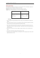
User Manual of Network Video Recorder 5.1 Configuring Parameters Purpose: By configuring the parameters you can define the parameters which affect the image quality, such as the transmission stream type, the resolution and so on. Before you start: 1. Make sure that the HDD has already been installed. If not, please install a HDD and initialize it. (Menu > HDD > General) Figure 5. 1 HDD- General 2. Check the storage mode of the HDD. 1) Click Advanced to check the storage mode of the HDD.
User Manual of Network Video Recorder Figure 5. 3 Recording Parameters 2. Parameters Setting for Recording 1) Select Record tab page to configure. You can configure the stream type, the resolution, and other parameters on your demand. 2) Click the More Settings button to set the advanced parameters for recording and then click OK button to finish editing. Figure 5. 4 Recording Parameters-More Settings • Pre-record: The time you set to record before the scheduled time or event.
User Manual of Network Video Recorder • Redundant Record: Enabling redundant record means you save the recording files in the redundant HDD. See Chapter Configuring Redundant Recording. • Record Audio: Check the checkbox to enable or disable audio recording. • Video Stream: Main stream and sub-stream are selectable for recording. When you select sub-stream, you can record for a longer time with the same storage space. 3) Click Apply to save the settings.
User Manual of Network Video Recorder 5.2 Configuring Recording Schedule Purpose: Set the recording schedule, and then the camera automatically starts/stops recording according to the configured schedule. Steps: 1. Enter the Record Schedule interface. Menu > Record > Schedule 2. Configure Record Schedule 1) Select Record Schedule. Figure 5. 6 Record Schedule Different recording types are marked in different color icons. Continous: scheduled recording.
User Manual of Network Video Recorder Figure 5. 7 Recording Schedule Interface You can click the button to set the accurate time of the schedule. II. To schedule an all-day recording, check the checkbox after the All Day item. Figure 5. 8 Edit Schedule III. To arrange other schedule, leave the All Day checkbox blank and set the Start/End time. Up to 8 periods can be configured for each day. And the time periods cannot be overlapped each other. IV. Select the record type in the dropdown list.
User Manual of Network Video Recorder Figure 5. 9 Draw the Schedule II. Click the Apply button to validate the settings. 3. (Optional) If the settings can also be used to other channels, click Copy, and then choose the channel to which you want to copy. 4. Click Apply to save the settings.
User Manual of Network Video Recorder 5.3 Configuring Motion Detection Recording Purpose: Follow the steps to set the motion detection parameters. In the live view mode, once a motion detection event takes place, the NVR can analyze it and do many actions to handle it. Enabling motion detection function can trigger certain channels to start recording, or trigger full screen monitoring, audio warning, notify the surveillance center and so on.
User Manual of Network Video Recorder 7) Click OK to back to the upper level menu. 8) Exit the Motion Detection menu. 3. Edit the Motion Detection Record Schedule. For the detailed information of schedule configuration, see Chapter 5.2 Configuring Recording Schedule.
User Manual of Network Video Recorder 5.4 Configuring Alarm Triggered Recording Purpose: Follow the procedure to configure alarm triggered recording. Steps: 1. Enter the Alarm setting interface. Menu > Configuration > Alarm Figure 5. 12 Alarm Settings 2. Click Alarm Input tab and set the alarm parameters. Figure 5. 13 Alarm Settings- Alarm Input 1) Select Alarm Input number and configure alarm parameters. 2) Choose N.O (normally open) or N.C (normally closed) for alarm type.
User Manual of Network Video Recorder Figure 5. 14 Alarm Settings 5) Choose the alarm triggered recording channel. 6) Check the checkbox to select channel. 7) Click Apply to save settings. 8) Click OK to back to the upper level menu. Repeat the above steps to configure other alarm input parameters. If the settings can also be applied to other alarm inputs, click Copy and choose the alarm input number. Figure 5. 15 Copy Alarm Input 3.
User Manual of Network Video Recorder 5.5 Configuring VCA Event Recording Purpose: The event triggered recording can be configured through the menu.
User Manual of Network Video Recorder Figure 5. 17 Set Trigger Camera of VCA Alarm The PTZ Linking function is only available for the VCA settings of IP cameras. 4. Enter Record Schedule settings interface (Menu > Record > Schedule > Record Schedule), and then set VCA as the record type. For details, see step 2 in Chapter 5.2 Configuring Recording Schedule. 5.6 Manual Recording Purpose: Follow the steps to set parameters for the manual record. Using manual record, you need to manually cancel the record.
User Manual of Network Video Recorder 5.7 Configuring Holiday Recording Purpose: Follow the steps to configure the record schedule on holiday for that year. You may want to have different plan for recording on holiday. Steps: 1. Enter the Record setting interface. Menu > Record > Holiday Figure 5. 19 Holiday Settings 2. Enable Edit Holiday schedule. 1) Click to enter the Edit interface. Figure 5. 20 Edit Holiday Settings 2) Check the checkbox after Enable Holiday. 3) Select Mode from the dropdown list.
User Manual of Network Video Recorder 5.8 Configuring Redundant Recording Purpose: Enabling redundant recording, which means saving the recording files not only in the R/W HDD but also in the redundant HDD, will effectively enhance the data safety and reliability. . Steps: 1. Enter HDD Information interface. Menu > HDD Figure 5. 21 HDD General 2. Select the HDD and click 1) to enter the Local HDD Settings interface. Set the HDD property to Redundancy. Figure 5.
User Manual of Network Video Recorder Figure 5. 23 Record Parameters 2) Check the checkbox of Redundant Record. 3) Click OK to save settings and back to the upper level menu. Repeat the above steps for configuring other channels.
User Manual of Network Video Recorder 5.9 Configuring HDD Group for Recording Purpose: You can group the HDDs and save the record files in certain HDD group. Steps: 1. Enter HDD setting interface. Menu > HDD Figure 5. 24 HDD General 2. Select Advanced on the left side menu. Figure 5. 25 Storage Mode Check whether the storage mode of the HDD is Group. If not, set it to Group. For detailed information, please refer to Chapter 12.3 Managing HDD Group. 3. Select General in the left side menu. 4.
User Manual of Network Video Recorder 5.10 Files Protection Purpose: You can lock the recording files or set the HDD property to Read-only to protect the record files from being overwritten. 5.10.1 Locking the Recording Files Lock File when Playback Steps: 1. Enter Playback interface. Menu> Playback 2. Check the checkbox of channel(s) in the channel list and then double-click to select a date on the calendar. Figure 5. 26 Normal Playback 3.
User Manual of Network Video Recorder Figure 5. 27 Locked File Management In the File Management interface, you can also click to change it to to unlock the file and the file is not protected. l Lock File when Export Steps: 1. Enter Export setting interface. Menu > Export Figure 5. 28 Export 2. Select the channels you want to investigate by checking the checkbox to 3. Configure the record type, file type start/end time. 4. Click Search to show the results. 79 .
User Manual of Network Video Recorder Figure 5. 29 Export- Search Result 5. Protect the record files. 1) Find the record files you want to protect, and then click the icon which will turn to that the file is locked. The record files of which the recording is still not completed cannot be locked. to change it to 2) Click to unlock the file and the file is not protected. Figure 5. 30 Unlocking Attention 5.10.2 Setting HDD Property to Read-only Steps: 1. Enter HDD setting interface.
User Manual of Network Video Recorder Figure 5. 32 HDD General- Editing To edit HDD property, you need to set the storage mode of the HDD to Group. See Chapter 12.3 Managing HDD Group. 3. Set the HDD property to Read-only. 4. Click OK to save settings and back to the upper level menu. l You cannot save any files in a Read-only HDD. If you want to save files in the HDD, change the property to R/W. l If there is only one HDD and is set to Read-only, the NVR can’t record any files.
User Manual of Network Video Recorder Chapter 6 Playback 82
User Manual of Network Video Recorder 6.1 Playing Back Record Files 6.1.1 Instant Playback Purpose: Play back the recorded video files of a specific channel in the live view mode. Channel switch is supported. Instant playback by channel Step: Choose a channel in live view mode and click the button in the quick setting toolbar. In the instant playback mode, only record files recorded during the last five minutes on this channel will be played back. Figure 6. 1 Instant Playback Interface 6.1.
User Manual of Network Video Recorder Figure 6. 2 Right-click Menu under Live View Pressing numerical buttons will switch playback to the corresponding channels during playback process. Playback by Time Purpose: Play back video files recorded in specified time duration. Multi-channel simultaneous playback and channel switch are supported. Steps: 1. Enter playback interface. Menu > Playback 2. Check the checkbox of channel(s) in the channel list and then double-click to select a date on the calendar.
User Manual of Network Video Recorder Playback Interface You can use the toolbar in the bottom part of Playback interface to control playing progress. Figure 6. 4 Playback Interface Click the channel(s) to execute simultaneous playback of multiple channels. Figure 6. 5 Toolbar of Playback l The indicates the start/end time of the record. l Playback progress bar: use the mouse to click any point of the progress bar or drag the progress bar to locate specific frames. Table 6.
User Manual of Network Video Recorder 6.1.3 Playing Back by Event Search Purpose: Play back record files on one or several channels searched out by event type (e.g., alarm input, motion detection and VCA). Steps: 1. Enter the Playback interface. Menu > Playback 2. Select the Event in the drop-down list on the top-left side. 3. Select Alarm Input, Motion or VCA as the event type. Here we take playback by VCA as the example. Figure 6. 6 Motion Search Interface 4.
User Manual of Network Video Recorder Figure 6. 7 Interface of Playback by Event You can click or button to select the previous or next event. Please refer to Table 6. 1 for the description of buttons on the toolbar. 6.1.4 Playing Back by Tag Purpose: Video tag allows you to record related information like people and location of a certain time point during playback. You can use video tag(s) to search for record files and position time point. Before playing back by tag: 1. Enter Playback interface.
User Manual of Network Video Recorder Figure 6. 8 Interface of Playback by Time Click button to add default tag. Click button to add customized tag and input tag name. Max. 64 tags can be added to a single video file. 3. Tag management. Click button to enter the File Management interface and click Tag to manage the tags. You can check, edit and delete tag(s). Figure 6.
User Manual of Network Video Recorder Playing back by Tag Steps: 1. Select the Tag from the drop-down list in the Playback interface. 2. Choose channels, edit start time and end time, and then click Search to enter Search Result interface. to search the tag on your command. You can enter keyword in the textbox 3. Click button to play back the selected tag file. You can click the Back button to back to the search interface. Figure 6.
User Manual of Network Video Recorder Events > Intrusion Detection. Figure 6. 11 Setting Intrusion Detection on IP Camera 2. Configure the required parameters of intrusion detection, including area, arming schedule and linkage methods. Refer to the user manual of smart IP camera for detailed instructions. Steps: 1. Enter Playback interface. Menu > Playback 2. Select the Smart in the drop-down list on the top-left side. 3. Select a camera in the camera list. 4.
User Manual of Network Video Recorder l Line Crossing Detection Select the l button , and click on the image to specify the start point and end point of the line. Intrusion Detection Click the button, and specify 4 points to set a quadrilateral region for intrusion detection. Only one region can be set. l Motion Detection Click the button and then click and draw the mouse to set the detection area manually. You can also click the button to set the full screen as the detection area. 6.
User Manual of Network Video Recorder 6.1.6 Playing Back by System Logs Purpose: Play back record file(s) associated with channels after searching system logs. Steps: 1. Enter Log Information interface. Menu > Maintenance > Log Information 2. Click Log Search tab to enter Playback by System Logs. Set search time and type and click Search button. Figure 6. 15 System Log Search Interface 3. Choose a log with record file and click button to enter Playback interface. Figure 6.
User Manual of Network Video Recorder Figure 6. 17 Interface of Playback by Log 6.1.7 Playing Back External File Purpose: Perform the following steps to look up and play back files in the external devices. Steps: 1. Enter Tag Search interface. Menu > Playback 2. Select the External File in the drop-down list on the top-left side. The files are listed in the right-side list. You can click the 3. Select and click the button to refresh the file list. button to play back it.
User Manual of Network Video Recorder 6.1.8 Playing Back by Sub-periods Purpose: The video files can be played in multiple sub-periods simultaneously on the screens. Steps: 1. Enter Playback interface. Menu > Playback 2. Select Sub-periods from the drop-down list in the upper-left corner of the page to enter the Sub-periods Playback interface. 3. Select a date and start playing the video file. 4. Select the Split-screen Number from the dropdown list. Up to 16 screens are configurable. Figure 6.
User Manual of Network Video Recorder Chapter 7 Backup 95
User Manual of Network Video Recorder 7.1 Backing up Record Files 7.1.1 Quick Export Purpose: Export record files to backup device(s) quickly. Steps: 1. Enter Video Export interface. Menu > Export > Normal Choose the channel(s) you want to back up and click Quick Export button. The time duration of record files on a specified channel cannot exceed one day. Otherwise, the message box “Max. 24 hours are allowed for quick export.” will pop up. Figure 7. 1 Quick Export Interface 2.
User Manual of Network Video Recorder Figure 7. 2 Quick Export using USB1-1 Stay in the Exporting interface until all record files are exported. Figure 7. 3 Export Finished 4. Check backup result. The Player player.exe will be exported automatically during record file export. Figure 7.
User Manual of Network Video Recorder 7.1.2 Backing up by Normal Video Search Purpose: The record files can be backup to various devices, such as USB devices (USB flash drives, USB HDDs, USB writer), SATA writer and e-SATA HDD. Backup using USB flash drives and USB HDDs Steps: 1. Enter Export interface. Menu>Export>Normal 2. Select the cameras to search. 3. Set search condition and click Search button to enter the search result interface. The matched video files are displayed in Chart or List display mode.
User Manual of Network Video Recorder Figure 7. 6 Result of Normal Video Search for Backup 5. Export the video files or picture files. Click Export All button to export all the files. Or you can select recording files you want to back up, and click Export button to enter Export interface. If the inserted USB device is not recognized: • Click the Refresh button. • Reconnect device. • Check for compatibility from vendor. You can also format USB flash drives or USB HDDs via the device. Figure 7.
User Manual of Network Video Recorder Figure 7. 8 Export Finished The backup of video files using USB writer or SATA writer has the same operating instructions. Please refer to steps described above. 7.1.3 Backing up by Event Search Purpose: Back up event-related record files using USB devices (USB flash drives, USB HDDs, USB writer), SATA writer or eSATA HDD. Quick Backup and Normal Backup are supported. Steps: 1. Enter Export interface. Menu > Export > Event 2. Select the cameras to search. 3.
User Manual of Network Video Recorder Figure 7. 10 Result of Event Search 6. Export the video files. Please refer to step5 of Chapter 7.1.2 Backing up by Normal Video Search for details. 7.1.4 Backing up Video Clips Purpose: You may also select video clips in playback mode to export directly during Playback, using USB devices (USB flash drives, USB HDDs, USB writer), SATA writer or eSATA HDD. Steps: 1. Enter Playback interface. Please refer to Chapter 6.1 Playing Back Record Files. 2.
User Manual of Network Video Recorder 7.2 Managing Backup Devices Management of USB flash drives and USB HDDs Steps: 1. Enter the Export interface. Figure 7. 12 Storage Device Management 2. Backup device management. Click New Folder button if you want to create a new folder in the backup device. Select a record file or folder in the backup device and click button if you want to delete it. Click Erase button if you want to erase the files from a re-writable CD/DVD.
User Manual of Network Video Recorder Chapter 8 Alarm Settings 103
User Manual of Network Video Recorder 8.1 Setting Motion Detection Alarm Steps: 1. Enter Motion Detection interface of Camera Management and choose a camera you want to set up motion detection. Menu > Camera > Motion 2. Set up detection area and sensitivity. Tick Enable Motion Detection, and use the mouse to draw detection area(s) and drag the sensitivity bar to set sensitivity. By default, the motion detection is enabled and configured in full screen. Click button and set alarm response actions.
User Manual of Network Video Recorder Time periods shall not be repeated or overlapped. Figure 8. 3 Set Arming Schedule of Motion Detection 5. Click Handling tab to set up alarm response actions of motion alarm (please refer to Chapter 8.6 Setting Alarm Response Actions). 6. If you want to set motion detection for another channel, repeat the above steps or just click Copy in the Motion Detection interface to copy the above settings to it.
User Manual of Network Video Recorder 8.2 Setting Sensor Alarms Purpose: Set the handling action of an external sensor alarm. Steps: 1. Enter Alarm Settings of System Configuration and select an alarm input. Menu> Configuration> Alarm Select Alarm Input tab to enter Alarm Input Settings interface. Figure 8. 4 Alarm Status Interface of System Configuration 2. Set up the handling action of the selected alarm input. Check the Enable checkbox and click Settings button to set up its alarm response actions.
User Manual of Network Video Recorder Figure 8. 6 Set Arming Schedule of Alarm Input Choose one day of a week and Max. eight time periods can be set within each day, and click Apply to save the settings. Time periods shall not be repeated or overlapped. Repeat the above steps to set up arming schedule of other days of a week. You can also use Copy button to copy an arming schedule to other days. 5. Select Linkage Action tab to set up alarm response actions of the alarm input (please refer to Chapter 8.
User Manual of Network Video Recorder inputs to copy the settings to them. Figure 8.
User Manual of Network Video Recorder 8.3 Detecting Video Loss Alarm Purpose: Detect video loss of a channel and take alarm response action(s). Steps: 1. Enter Video Loss interface of Camera Management and select a channel you want to detect. Menu > Camera > Video Loss Figure 8. 9 Video Loss Setup Interface 2. Set up handling action of video loss. Check the checkbox of “Enable Video Loss Alarm”, and click button to set up handling action of video loss. 3. Set up arming schedule of the handling actions.
User Manual of Network Video Recorder 8.4 Detecting Video Tampering Alarm Purpose: Trigger alarm when the lens is covered and take alarm response action(s). Steps: 1. Enter Video Tampering interface of Camera Management and select a channel you want to detect video tampering. Menu> Camera> Video Tampering Figure 8. 11 Video Tampering Setup Interface 2. Set the video tampering handling action of the channel. Check the checkbox of Enable Video Tampering Detection.
User Manual of Network Video Recorder Figure 8. 12 Set Arming Schedule of Video Tampering 4. Select Linkage Action tab to set up alarm response actions of video tampering alarm (please refer to Chapter 8.6 Setting Alarm Response Actions). 5. Click the OK button to complete the video tampering settings of the channel.
User Manual of Network Video Recorder 8.5 Handling Exceptions Alarm Purpose: Exception settings refer to the handling action of various exceptions, e.g. • • • • • • • HDD Full: The HDD is full. HDD Error: Writing HDD error or unformatted HDD. Network Disconnected: Disconnected network cable. IP Conflicted: Duplicated IP address. Illegal Login: Incorrect user ID or password. Record Exception: No space for saving recorded files.
User Manual of Network Video Recorder 8.6 Setting Alarm Response Actions Purpose: Alarm response actions will be activated when an alarm or exception occurs, including Event Hint Display, Full Screen Monitoring, Audible Warning (buzzer), Notify Surveillance Center, Upload Picture to FTP, Trigger Alarm Output and Send Email. Event Hint Display When an event or exception happens, a hint can be displayed on the lower-left corner of live view image. And you can click the hint icon to check the details.
User Manual of Network Video Recorder You must select during “Trigger Channel” settings the channel(s) you want to make full screen monitoring. Audible Warning Trigger an audible beep when an alarm is detected. Notify Surveillance Center Sends an exception or alarm signal to remote alarm host when an event occurs. The alarm host refers to the PC installed with Remote Client. The alarm signal will be transmitted automatically at detection mode when remote alarm host is configured.
User Manual of Network Video Recorder Figure 8. 17 Set Arming Schedule of Alarm Output 3. Repeat the above steps to set up arming schedule of other days of a week. You can also use Copy button to copy an arming schedule to other days. Click the OK button to complete the video tampering settings of the alarm output No. 4. You can also copy the above settings to another channel. Figure 8.
User Manual of Network Video Recorder 8.7 Triggering or Clearing Alarm Output Manually Purpose: Sensor alarm can be triggered or cleared manually. If “Manually Clear” is selected in the dropdown list of dwell time of an alarm output, the alarm can be cleared only by clicking Clear button in the following interface. Steps: Select the alarm output you want to trigger or clear and make related operations. Menu> Manual> Alarm Click Trigger/Clear button if you want to trigger or clear an alarm output.
User Manual of Network Video Recorder Chapter 9 VCA Alarm 117
User Manual of Network Video Recorder l All VCA detection must be supported by the connected IP camera. 9.1 Face Detection Purpose: Face detection function detects the face appears in the surveillance scene, and some certain actions can be taken when the alarm is triggered. Steps: 1. Enter the VCA settings interface. Menu> Camera> VCA 2. Select the camera to configure the VCA. You can click the checkbox of Save VCA Picture to save the captured pictures of VCA detection. Figure 9. 1 Face Detection 3.
User Manual of Network Video Recorder 9.2 Line Crossing Detection Purpose: This function can be used for detecting people, vehicles and objects cross a set virtual line. The line crossing direction can be set as bidirectional, from left to right or from right to left. And you can set the duration for the alarm response actions, such as full screen monitoring, audible warning, etc. Steps: 1. Enter the VCA settings interface. Menu> Camera> VCA 2. Select the camera to configure the VCA.
User Manual of Network Video Recorder Up to 4 rules can be configured. Figure 9. 4 Draw Line for Line Crossing Detection 8. Click Apply to activate the settings.
User Manual of Network Video Recorder 9.3 Intrusion Detection Purpose: Intrusion detection function detects people, vehicle or other objects which enter and loiter in a pre-defined virtual region, and some certain actions can be taken when the alarm is triggered. Steps: 1. Enter the VCA settings interface. Menu> Camera> VCA 2. Select the camera to configure the VCA. You can click the checkbox of Save VCA Picture to save the captured pictures of VCA detection. 3.
User Manual of Network Video Recorder Figure 9. 6 Draw Area for Intrusion Detection 8. Click Apply to save the settings.
User Manual of Network Video Recorder 9.4 Region Entrance Detection Purpose: Region entrance detection function detects people, vehicle or other objects which enter a pre-defined virtual region from the outside place, and some certain actions can be taken when the alarm is triggered. Steps: 1. Enter the VCA settings interface. Menu> Camera> VCA 2. Select the camera to configure the VCA. You can click the checkbox of Save VCA Picture to save the captured pictures of VCA detection. 3.
User Manual of Network Video Recorder 9.5 Region Exiting Detection Purpose: Region exiting detection function detects people, vehicle or other objects which exit from a pre-defined virtual region, and some certain actions can be taken when the alarm is triggered. l Please refer to the Chapter 9.4 Region Entrance Detection for operating steps to configure the region exiting detection. l Up to 4 rules can be configured. 9.
User Manual of Network Video Recorder l Please refer to the Chapter 9.3 Intrusion Detection for operating steps to configure the fast moving detection. l The Sensitivity in the Rule Settings defines the moving speed of the object which can trigger the alarm. The higher the value is, the more easily a moving object can trigger the alarm. l Up to 4 rules can be configured. 9.9 Parking Detection Purpose: Parking detection function detects illegal parking in places such as highway, one-way street, etc.
User Manual of Network Video Recorder l Please refer to the Chapter 9.3 Intrusion Detection for operating steps to configure the object removal detection. l The Threshold [5s-20s] in the Rule Settings defines the time of the objects removed from the region. If you set the value as 10, alarm is triggered after the object disappears from the region for 10s. And the Sensitivity defines the similarity degree of the background image.
User Manual of Network Video Recorder 6. Click Apply to activate the settings. 9.13 Sudden Scene Change Detection Purpose: Scene change detection function detects the change of surveillance environment affected by the external factors; such as the intentional rotation of the camera, and some certain actions can be taken when the alarm is triggered. l Please refer to the Chapter Face Detection for operating steps to configure the scene change detection.
User Manual of Network Video Recorder Chapter 10 VCA Search 128
User Manual of Network Video Recorder With the configured VCA detection, the NVR supports the VCA search for the behavior analysis, face capture, people counting and heat map results. 10.1 Face Search Purpose: When there are detected face picture captured and saved in HDD, you can enter the Face Search interface to search the picture and play the picture related video file according to the specified conditions. Before you start: Please refer to Section Face Detection for configuring the face detection.
User Manual of Network Video Recorder Figure 10. 2 Face Search Interface 5. Play the face picture related video file. You can double click on a face picture to play its related video file in the view window on the top right, or select a picture item and click to play it. to stop the playing, or click / to play the previous/next file. You can also click 6.
User Manual of Network Video Recorder 10.2 Behavior Search Purpose: The behavior analysis detects a series of suspicious behavior based on VCA detection, and certain linkage methods will be enabled if the alarm is triggered. Steps: 1. Enter the Behavior Search interface. Menu>VCA Search> Behavior Search 2. Select the camera (s) for the behavior search. 3. Specify the start time and end time for searching the matched pictures. Figure 10. 4 Behavior Search Interface 4.
User Manual of Network Video Recorder Figure 10. 5 Behavior Search Results 6. Play the behavior analysis picture related video file. You can double click on a picture from the list to play its related video file in the view window on the top right, or select a picture item and click to play it. to stop the playing, or click / to play the previous/next file. You can also click 7.
User Manual of Network Video Recorder Figure 10. 6 Plate Search 4. Select the country from the drop-down list for searching the location of the vehicle plate. 5. Input the plate No. in the field for search. 7. Click Search to start searching. The search results of detected vehicle plate pictures are displayed in list or in chart. Please refer to the Step7-Step8 of Section 10.1 Face Search for the operation of the search results. 10.
User Manual of Network Video Recorder Figure 10. 7 People Counting Interface 6. You can click the Export button to export the statistics report in excel format.
User Manual of Network Video Recorder 10.5 Heat Map Purpose: Heat map is a graphical representation of data represented by colors. The heat map function is usually used to analyze the visit times and dwell time of customers in a configured area. The heat map function must be supported by the connected IP camera and the corresponding configuration must be set. Steps: 1. Enter the Heat Map interface. Menu>VCA Search> Heat Map 2. Select the camera for the heat map processing. 3.
User Manual of Network Video Recorder Chapter 11 Network Settings 136
User Manual of Network Video Recorder 11.1 Configuring General Settings Purpose: Network settings must be properly configured before you operate NVR over network. Steps: 1. Enter the Network Settings interface. Menu > Configuration > Network 2. Select the General tab. Figure 11. 1 Network Settings Interface 3. In the General Settings interface, you can configure the following settings: Working Mode, NIC Type, IPv4 Address, IPv4 Gateway, MTU and DNS Server.
User Manual of Network Video Recorder Configuring Advanced Settings 11.1.1 PPPoE Settings Purpose: Your NVR also allows access by Point-to-Point Protocol over Ethernet (PPPoE). Steps: 1. Enter the Network Settings interface. Menu >Configuration> Network 2. Select the PPPoE tab to enter the PPPoE Settings interface, as shown in Figure 11. 2. Figure 11. 2 PPPoE Settings Interface 3. Check the PPPoE checkbox to enable this feature. 4. Enter User Name and Password for PPPoE access.
User Manual of Network Video Recorder scanning tool of your phone to quickly get the code by scanning the QR code below. Figure 11. 3 Cloud P2P Settings Interface 7. Click the Apply button to save and exit the interface. After configuration, you can access and manage the NVR by your mobile phone on which the Cloud P2P application is installed. 11.1.3 Configuring DDNS Purpose: If your NVR is set to use PPPoE as its default network connection, you may set Dynamic DNS (DDNS) to be used for network access.
User Manual of Network Video Recorder Figure 11. 4 IPServer Settings Interface • DynDNS: 1) Enter Server Address for DynDNS (i.e. members.dyndns.org). 2) In the NVR Domain Name text field, enter the domain obtained from the DynDNS website. 3) Enter the User Name and Password registered in the DynDNS website. Figure 11. 5 DynDNS Settings Interface • PeanutHull: Enter the User Name and Password obtained from the PeanutHull website. Figure 11.
User Manual of Network Video Recorder 2) In the NVR Domain Name text field, enter the domain obtained from the NO-IP website (www.no-ip.com). 3) Enter the User Name and Password registered in the NO-IP website. Figure 11. 7 NO-IP Settings Interface • SIMPLEDDNS: 1) Select the continent/country of the server on which the device is registered. 2) The Server Address of the SimpleDDNS server appears by default: www.simpleddns.com. 3) Enter the Device Domain Name.
User Manual of Network Video Recorder Figure 11. 9 Register an Account 2) Click to register an account if you do not have one and use the account to log in. Figure 11. 10 Register an Account 3) In the Device Management interface, click 142 to register the device.
User Manual of Network Video Recorder Figure 11. 11 Register the Device 4) Input Device Serial No., Device Domain (Device Name) and HTTP Port. And click OK to add the device. Ø Access the Device via Web Browser or Client Software After having successfully registered the device on the SimpleDDNS server, you can access your device via web browser or Client Software with the Device Domain Name (Device Name). l OPTION 1: Access the Device via Web Browser Open a web browser, and enter http:// www.
User Manual of Network Video Recorder Figure 11. 12 Access Device via client software 5. Click the Apply button to save the settings. After setting all the required parameters for the DDNS, you can view the connecting status of the device by checking the Status information. 11.1.4 Configuring NTP Server Purpose: Ensure the network connection of the PC (running FTP server) and the device is valid and correct. Run the FTP server on the PC and copy the firmware into the corresponding directory of your PC.
User Manual of Network Video Recorder The time synchronization interval can be set from1 to 10080min, and the default value is 60min. If the NVR is connected to a public network, you should use a NTP server that has a time synchronization function, such as the server at the National Time Center (IP Address: 210.72.145.44). If the NVR is setup in a more customized network, NTP software can be used to establish a NTP server used for time synchronization. 11.1.
User Manual of Network Video Recorder Figure 11. 15 More Settings Interface 3. Enter Alarm Host IP and Alarm Host Port in the text fields. The Alarm Host IP refers to the IP address of the remote PC on which the Network Video Surveillance Software is installed, and the Alarm Host Port must be the same as the alarm monitoring port configured in the software. 4. Click the Apply button to save and exit the interface. 11.1.
User Manual of Network Video Recorder 1. Enter the Network Settings menu Menu >Configuration> Network 2. Select the More Settings tab to enter the More Settings menu, as shown in Figure 11. 15. Figure 11. 17 RTSP Settings Interface 3. Enter the RTSP port in the text field of RTSP Service Port. The default RTSP port is 554, and you can change it according to different requirements. 4. Click the Apply button to save and exit the menu. 11.1.
User Manual of Network Video Recorder 1. Enter the Network Settings interface. Menu >Configuration> Network 2. Set the IPv4 Address, IPv4 Subnet Mask, IPv4 Gateway and the Preferred DNS Server in the Network Settings men. Figure 11. 19 Network Settings Interface 3. Click Apply to save the settings. 4. Select the Email tab to enter the Email Settings interface. Figure 11. 20 Email Settings Interface 5.
User Manual of Network Video Recorder E-mail Test: Sends a test message to verify that the SMTP server can be reached. 6. Click Apply button to save the Email settings. 7. You can click Test button to test whether your Email settings work. The corresponding Attention message box will pop up. Refer to Figure 11. 21. Figure 11. 21 Email Testing Attention 11.1.
User Manual of Network Video Recorder 1) Select Auto in the drop-down list of Mapping Type. 2) Click Apply button to save the settings. 3) You can click Refresh button to get the latest status of the port mapping. Figure 11. 23 UPnP™ Settings Finished-Auto OPTION 2: Manual If you select Manual as the mapping type, you can edit the external port on your demand by clicking to activate the External Port Settings dialog box. Steps: 1) Select Manual in the drop-down list of Mapping Type.
User Manual of Network Video Recorder Figure 11. 25 UPnP™ Settings Finished-Manual l Manual Mapping If your router does not support the UPnPTM function, perform the following steps to map the port manually in an easy way. Before you start: Make sure the router support the configuration of internal port and external port in the interface of Forwarding. Steps: 1. Enter the Network Settings interface. Menu > Configuration > Network 2. Select the NAT tab to enter the port mapping interface. 3.
User Manual of Network Video Recorder Figure 11. 27 Setting Virtual Server Item The above virtual server setting interface is for reference only, it may be different due to different router manufactures. Please contact the manufacture of router if you have any problems with setting virtual server. 11.2 Checking Network Traffic Purpose: You can check the network traffic to obtain real-time information of NVR such as linking status, MTU, sending/receiving rate, etc. Steps: 1.
User Manual of Network Video Recorder 11.3 Configuring Network Detection Purpose: You can obtain network connecting status of NVR through the network detection function, including network delay, packet loss, etc. 11.3.1 Testing Network Delay and Packet Loss Steps: 1. Enter the Network Traffic interface. Menu >Maintenance>Net Detect 2. Click the Network Detection tab to enter the Network Detection menu, as shown in Figure 11. 29. Figure 11. 29 Network Detection Interface 3.
User Manual of Network Video Recorder Click Refresh button if the connected local backup device cannot be displayed. When it fails to detect the backup device, please check whether it is compatible with the NVR. You can format the backup device if the format is incorrect. Figure 11. 31 Export Network Packet 4. Click Export button to start exporting. 5. After the exporting is complete, click OK to finish the packet export, as shown in Figure 11. 32. Figure 11.
User Manual of Network Video Recorder Figure 11. 33 Network Status Checking If the network is normal the following message box pops out. Figure 11. 34 Network status checking result If the message box pops out with other information instead of this one, you can click Network button to show the quick setting interface of the network parameters. 11.3.4 Checking Network Statistics Purpose: You can check the network status to obtain the real-time information of NVR. Steps: 1.
User Manual of Network Video Recorder Figure 11. 35 Network Stat. Interface 3. Check the bandwidth of IP Camera, bandwidth of Remote Live View, bandwidth of Remote Playback, bandwidth of Net Receive Idle and bandwidth of Net Send Idle. 4. You can click Refresh to get the newest status.
User Manual of Network Video Recorder Chapter 12 HDD Management 157
User Manual of Network Video Recorder 12.1 Initializing HDDs Purpose: A newly installed hard disk drive (HDD) must be initialized before it can be used with your NVR. A message box pops up when the NVR starts up if there exits any uninitialized HDD. Figure 12. 1 Message Box of Uninitialized HDD Click Yes button to initialize it immediately or you can perform the following steps to initialize the HDD. Steps: 1. Enter the HDD Information interface. Menu > HDD> General Figure 12.
User Manual of Network Video Recorder Figure 12. 5 HDD Status Changes to Normal Initializing the HDD will erase all data on it.
User Manual of Network Video Recorder 12.2 Managing Network HDD Purpose: You can add the allocated NAS or disk of IP SAN to NVR, and use it as network HDD. Steps: 1. Enter the HDD Information interface. Menu > HDD>General Figure 12. 6 HDD Information Interface 2. Click the Add button to enter the Add NetHDD interface, as shown in Figure 12. 7. Figure 12. 7 HDD Information Interface 3. Add the allocated NetHDD. 4. Select the type to NAS or IP SAN. 5. Configure the NAS or IP SAN settings.
User Manual of Network Video Recorder Figure 12. 8 Add NAS Disk • Add IP SAN: 1) Enter the NetHDD IP address in the text field. 2) Click the Search button to search the available IP SAN disks. 3) Select the IP SAN disk from the list shown below. 4) Click the OK button to add the selected IP SAN disk. Up to 1 IP SAN disk can be added. Figure 12. 9 Add IP SAN Disk 6. After having successfully added the NAS or IP SAN disk, return to the HDD Information menu. The added NetHDD will be displayed in the list.
User Manual of Network Video Recorder Figure 12.
User Manual of Network Video Recorder 12.3 Managing HDD Group 12.3.1 Setting HDD Groups Purpose: Multiple HDDs can be managed in groups. Video from specified channels can be recorded onto a particular HDD group through HDD settings. Steps: 1. Enter the Storage Mode interface. Menu > HDD > Advanced 2. Set the Mode to Group, as shown in Figure 12. 11. Figure 12. 11 Storage Mode Interface 3. Click the Apply button and the following Attention box will pop up. Figure 12. 12 Attention for Reboot 4.
User Manual of Network Video Recorder Figure 12. 13 Local HDD Settings Interface 7. Select the Group number for the current HDD. The default group No. for each HDD is 1. 8. Click the OK button to confirm the settings. Figure 12. 14 Confirm HDD Group Settings 9. In the pop-up Attention box, click the Yes button to finish the settings. 12.3.2 Setting HDD Property Purpose: The HDD property can be set to redundancy, read-only or read/write (R/W).
User Manual of Network Video Recorder Figure 12. 15 Set HDD Property 3. Set the HDD property to R/W, Read-only or Redundancy. 4. Click the OK button to save the settings and exit the interface. 5. In the HDD Information menu, the HDD property will be displayed in the list. At least 2 hard disks must be installed on your NVR when you want to set a HDD to Redundancy, and there is one HDD with R/W property.
User Manual of Network Video Recorder 12.4 Configuring Quota Mode Purpose: Each camera can be configured with allocated quota for the storage of recorded files. Steps: 1. Enter the Storage Mode interface. Menu > HDD > Advanced 2. Set the Mode to Quota, as shown in Figure 12. 16. The NVR must be rebooted to enable the changes to take effect. Figure 12. 16 Storage Mode Settings Interface 3. Select a camera for which you want to configure quota. 4. Enter the storage capacity in the text fields of Max.
User Manual of Network Video Recorder Figure 12. 18 Copy Settings to Other Camera(s) 6. Select the camera (s) to be configured with the same quota settings. You can also click the checkbox of IP Camera to select all cameras. 7. Click the OK button to finish the Copy settings and back to the Storage Mode interface. 8. Click the Apply button to apply the settings. If the quota capacity is set to 0, then all cameras will use the total capacity of HDD for record.
User Manual of Network Video Recorder 12.5 Checking HDD Status Purpose: You may check the status of the installed HDDs on NVR so as to take immediate check and maintenance in case of HDD failure. Checking HDD Status in HDD Information Interface Steps: 1. Enter the HDD Information interface. Menu > HDD>General 2. Check the status of each HDD which is displayed on the list, as shown in Figure 12. 19. Figure 12. 19 View HDD Status (1) If the status of HDD is Normal or Sleeping, it works normally.
User Manual of Network Video Recorder 12.6 HDD Detection Purpose: The device provides the HDD detection function such as the adopting of the S.M.A.R.T. and the Bad Sector Detection technique. The S.M.A.R.T. (Self-Monitoring, Analysis and Reporting Technology) is a monitoring system for HDD to detect and report on various indicators of reliability in the hopes of anticipating failures. S.M.A.R.T. Settings Steps: 1. Enter the S.M.A.R.T Settings interface. Menu > Maintenance >HDD Detect 2.
User Manual of Network Video Recorder Figure 12. 22 Bad Sector Detection And you can click Error info button to see the detailed damage information. And you can also pause/resume or cancel the detection.
User Manual of Network Video Recorder 12.7 Configuring HDD Error Alarms Purpose: You can configure the HDD error alarms when the HDD status is Uninitialized or Abnormal. Steps: 1. Enter the Exception interface. Menu > Configuration > Exceptions 2. Select the Exception Type to HDD Error from the dropdown list. 3. Click the checkbox(s) below to select the HDD error alarm type (s), as shown in Figure 12. 23.
User Manual of Network Video Recorder Chapter 13 Camera Settings 172
User Manual of Network Video Recorder 13.1 Configuring OSD Settings Purpose: You can configure the OSD (On-screen Display) settings for the camera, including date /time, camera name, etc. Steps: 1. Enter the OSD Configuration interface. Menu > Camera > OSD 2. Select the camera to configure OSD settings. 3. Edit the Camera Name in the text field. 4. Configure the Display Name, Display Date and Display Week by clicking the checkbox. 5. Select the Date Format, Time Format and Display Mode. Figure 13.
User Manual of Network Video Recorder 13.2 Configuring Privacy Mask Purpose: You are allowed to configure the four-sided privacy mask zones that cannot be viewed by the operator. The privacy mask can prevent certain surveillance areas to be viewed or recorded. Steps: 1. Enter the Privacy Mask Settings interface. Menu > Camera >Privacy Mask 2. Select the camera to set privacy mask. 3. Click the checkbox of Enable Privacy Mask to enable this feature. Figure 13. 2 Privacy Mask Settings Interface 4.
User Manual of Network Video Recorder 13.3 Configuring Video Parameters Steps: 1. Enter the Image Settings interface. Menu > Camera >Image Figure 13. 4 Image Settings Interface 2. Select the camera to set image parameters. 3. You can click on the arrow to change the value of each parameter. 4. Click the Apply button to save the settings.
User Manual of Network Video Recorder Chapter 14 NVR Management Maintenance 176 and
User Manual of Network Video Recorder 14.1 Viewing System Information Steps: 1. Enter the System Information interface. Menu >Maintenance>System Info 2. You can click the Device Info, Camera, Record, Alarm, Network and HDD tabs to view the system information of the device. Figure 14.
User Manual of Network Video Recorder 14.2 Searching & Export Log Files Purpose: The operation, alarm, exception and information of the NVR can be stored in log files, which can be viewed and exported at any time. Steps: 1. Enter the Log Search interface. Menu > Maintenance > Log Information Figure 14. 2 Log Search Interface 2. Set the log search conditions to refine your search, including the Start Time, End Time, Major Type and Minor Type. 3. Click the Search button to start search log files. 4.
User Manual of Network Video Recorder Figure 14. 3 Log Search Results Up to 2000 log files can be displayed each time. 5. You can click the button of each log or double click it to view its detailed information, as shown in Figure 14. 4. And you can also click the button to view the related video files if available. Figure 14. 4 Log Details 6. If you want to export the log files, click the Export button on the Search Result interface to enter the Export menu, as shown in Figure 14. 5.
User Manual of Network Video Recorder Figure 14. 5 Export Log Files 7. Select the backup device from the dropdown list of Device Name. 8. Select the format of the log files to be exported. Up to 9 formats are selectable. 9. Click the Export to export the log files to the selected backup device. You can click the New Folder button to create new folder in the backup device, or click the Format button to format the backup device before log export.
User Manual of Network Video Recorder 14.3 Importing/Exporting IP Camera Info Purpose: The information of added IP camera can be generated into an excel file and exported to the local device for backup, including the IP address, manage port, password of admin, etc.. And the exported file can be edited on your PC, like adding or deleting the content, and copy the setting to other devices by importing the excel file to it. Steps: 1. Enter the camera management interface.
User Manual of Network Video Recorder 14.4 Importing/Exporting Configuration Files Purpose: The configuration files of the NVR can be exported to local device for backup; and the configuration files of one NVR can be imported to multiple NVR devices if they are to be configured with the same parameters. Steps: 1. Enter the Import/Export Configuration File interface. Menu > Maintenance >Import/Export Figure 14. 6 Import/Export Config File 2.
User Manual of Network Video Recorder 14.5 Upgrading System Purpose: The firmware on your NVR can be upgraded by local backup device or remote FTP server. 14.5.1 Upgrading by Local Backup Device Steps: 1. Connect your NVR with a local backup device where the update firmware file is located. 2. Enter the Upgrade interface. Menu >Maintenance>Upgrade 3. Click the Local Upgrade tab to enter the local upgrade menu, as shown in Figure 14. 7. Figure 14. 7 Local Upgrade Interface 4.
User Manual of Network Video Recorder directory as required. Steps: 1. Enter the Upgrade interface. Menu >Maintenance>Upgrade 2. Click the FTP tab to enter the local upgrade interface, as shown in Figure 14. 8. Figure 14. 8 FTP Upgrade Interface 3. Enter the FTP Server Address in the text field. 4. Click the Upgrade button to start upgrading. 5. After the upgrading is complete, reboot the NVR to activate the new firmware.
User Manual of Network Video Recorder 14.6 Restoring Default Settings Steps: 1. Enter the Default interface. Menu > Maintenance > Default Figure 14. 9 Restore Defaults 2. Select the restoring type from the following three options. Restore Defaults: Restore all parameters, except the network (including IP address, subnet mask, gateway, MTU, NIC working mode, default route, server port, etc.) and user account parameters, to the factory default settings.
User Manual of Network Video Recorder Chapter 15 Others 186
User Manual of Network Video Recorder 15.1 Configuring General Settings Purpose: You can configure the BNC output standard, VGA output resolution, mouse pointer speed through the Menu > Configuration > General interface. Steps: 1. Enter the General Settings interface. Menu >Configuration> General 2. Select the General tab. Figure 15. 1 General Settings Interface 3. Configure the following settings: • Language: The default language used is English.
User Manual of Network Video Recorder 15.2 Configuring DST Settings Steps: 1. Enter the General Settings interface. Menu >Configuration>General 2. Choose DST Settings tab. Figure 15. 2 DST Settings Interface You can check the checkbox before the Auto DST Adjustment item. Or you can manually check the Enable DST checkbox, and then you choose the date of the DST period.
User Manual of Network Video Recorder 15.3 Configuring More Settings for Device Parameters Steps: 1. Enter the General Settings interface. Menu >Configuration>General 2. Click the More Settings tab to enter the More Settings interface, as shown in Figure 15. 3. Figure 15. 3 More Settings Interface 3. Configure the following settings: • Device Name: Edit the name of NVR. • Device No.: Edit the serial number of NVR. The Device No. can be set in the range of 1~255, and the default No. is 255.
User Manual of Network Video Recorder 15.4 Managing User Accounts Purpose: There is a default account in the NVR: Administrator. The Administrator user name is admin and the password is set when you start the device for the first time. The Administrator has the permission to add and delete user and configure user parameters. 15.4.1 Adding a User Steps: 1. Enter the User Management interface. Menu >Configuration>User Figure 15. 4 User Management Interface 2.
User Manual of Network Video Recorder Address. Password: Set the password for the user account. STRONG PASSWORD RECOMMENDED– We highly recommend you create a strong password of your own choosing (using a minimum of 8 characters, including upper case letters, lower case letters, numbers, and special characters) in order to increase the security of your product.
User Manual of Network Video Recorder 6. Set the operating permission of Local Configuration, Remote Configuration and Camera Configuration for the user. Local Configuration • Local Log Search: Searching and viewing logs and system information of NVR. • Local Parameters Settings: Configuring parameters, restoring factory default parameters and importing/exporting configuration files. • Local Camera Management: The adding, deleting and editing of IP cameras.
User Manual of Network Video Recorder Figure 15. 8 User List 3. Click the icon to delete the selected user account. 15.4.3 Editing a User For the added user accounts, you can edit the parameters. Steps: 1. Enter the User Management interface. Menu >Configuration>User 2. Select the user to be edited from the list, as shown in Figure 15. 8. 3. Click the icon to enter the Edit User interface, as shown in Figure 15. 9. Figure 15. 9 Edit User Interface 4. Edit the corresponding parameters.
User Manual of Network Video Recorder STRONG PASSWORD RECOMMENDED– We highly recommend you create a strong password of your own choosing (using a minimum of 8 characters, including upper case letters, lower case letters, numbers, and special characters) in order to increase the security of your product. And we recommend you reset your password regularly, especially in the high security system, resetting the password monthly or weekly can better protect your product. 5.
User Manual of Network Video Recorder 15.
User Manual of Network Video Recorder Glossary • Dual Stream: Dual stream is a technology used to record high resolution video locally while transmitting a lower resolution stream over the network. The two streams are generated by the DVR, with the main stream having a maximum resolution of 4CIF and the sub-stream having a maximum resolution of CIF. • HDD: Acronym for Hard Disk Drive. A storage medium which stores digitally encoded data on platters with magnetic surfaces.
User Manual of Network Video Recorder Troubleshooting l No image displayed on the monitor after starting up normally. Possible Reasons a) No VGA or HDMITM connections. b) Connection cable is damaged. c) Input mode of the monitor is incorrect. Steps 1. Verify the device is connected with the monitor via HDMITM or VGA cable. If not, please connect the device with the monitor and reboot. 2. Verify the connection cable is good.
User Manual of Network Video Recorder Possible Reasons a) Network failure, and the NVR and IP camera lost connections. b) The configured parameters are incorrect when adding the IP camera. c) Insufficient bandwidth. Steps 1. Verify the network is connected. 1) Enter the Network Traffic interface. Menu >Maintenance>Net Detect 2) Click the Network Detection tab to enter the Network Detection menu 3) Enter the destination address in the text field of Destination Address.
User Manual of Network Video Recorder device with the monitor via VGA or HDMITM interface and reboot the device, there is black screen with the mouse cursor. Connect the NVR with the monitor before startup via VGA or HDMITM interface, and manage the IP camera to connect with the device locally or remotely, the status of IP camera displays as Connect. Possible Reasons: After connecting the IP camera to the NVR, the image is output via the main spot interface by default. Steps: 1. Enable the output channel.
User Manual of Network Video Recorder 3) Enter the destination address in the text field of Destination Address. 4) Click Test button to start testing network delay and packet loss. The testing result pops up on the window. If there exists return information and the time value is little, the network is normal. 2. Verify the network between NVR and PC is connected. 1) Open the cmd window in the Start menu, or you can press “windows+R” shortcut key to open it.
User Manual of Network Video Recorder Select “Menu > Record > Parameters > Record”, and set the Stream Type as “Audio & Video”. 3. Verify the audio encoding standard of the IP camera is supported by the NVR. NVR supports G722.1 and G711 standards, and if the encoding parameter of the input audio is not one of the previous two standards, you can log in the IP camera to configure it to the supported standard. 4. Check if the fault is solved by the above steps. If it is solved, finish the process.
User Manual of Network Video Recorder Select “Menu > HDD > General” to view the HDD status, and verify the HDD is detected and can be read and written normally. 4. Check if the fault is solved by the above steps. If it is solved, finish the process. If not, please contact the engineer from our company to do the further process.
User Manual of Network Video Recorder List of Compatible IP Cameras l For the list, our company holds right to interpret. l ONVIF compatibility refers to the camera can be supported both when it uses the ONVIF protocol and its private protocols. Only ONVIF is supported refers to the camera can only be supported when it uses the ONVIF protocol. Only AXIS is supported refers to the function can only be supported when it uses the AXIS protocol.
User Manual of Network Video Recorder IP Camera Manufacturer or Model Version VB-M400 Ver.+1.0.0 Sub-stream Audio 1280×960 × √ VB-M6000D Ver.+1.0.0 1280×960 × × VB-M7000F Ver.+1.0.0 1280×960 × √ HLC_79AD V1.0.40 1600×1200 √ × DS-2CD883F-E V5.1.0 build 131202 2560×1920 √ √ V5.1.0 build 131202 2560×1920 √ √ DS-2CD8283F-E(I) V5.1.0 build 131202 2560×1920 √ √ DS-2CD886BF-E V4.0.3 build 120913 2560×1920 √ √ DS-2CD886MF-E V4.0.
User Manual of Network Video Recorder IP Camera Manufacturer or Model Version DS-2CD8264FWD-E(I) V5.1.0 build 131202 DS-2CD8264FWD-EZ Max. Sub-stream Audio 1280×720 √ √ V5.1.0 build 131202 1280×720 √ √ V5.1.2 build140116 1280×960 √ × V5.1.2 build140116 1280×960 √ √ V5.1.2 build140116 1280×960 √ × V5.1.2 build140116 1280×960 √ √ V5.1.2 build140116 2048×1536 √ × V5.1.2 build140116 2048×1536 √ √ V5.1.2 build140116 2048×1536 √ × V5.1.
User Manual of Network Video Recorder IP Camera Manufacturer or Model Version Protocol Max. Resolution Sub-stream Audio DS-2CD2710F-IS DS-2CD4012F DS-2CD4212F-IS(2.8-12mm) V5.1.3 build 140117 1280×960 √ √ V5.1.3 build 140117 1280×960 √ × V5.1.3 build 140117 1920×1080 √ √ V5.1.3 build 140117 1920×1080 √ √ V5.1.3 build 140117 2048×1536 √ √ V5.1.3 build 140117 2048×1536 √ × V5.1.3 build 140117 2048×1536 √ √ V5.1.3 build 140117 2048×1536 √ √ DS-2CD4212FWD-I V5.1.
User Manual of Network Video Recorder IP Camera Manufacturer or Model Version Protocol Max. Resolution Sub-stream Audio DS-2CD832F DS-2CD892PF/NF DS-2CD893PF-E DS-2CD893PFWD-E V5.1.0 build 131202 704×576 √ √ V5.1.0 build 131202 704×576 √ √ DS-2CD9121 V3.4.2 build 130718 1600×1200 √ × iDS-2CD9121 V3.4.2 build 130718 1600×1200 √ × iDS-2CD9121A V3.5.0 build130906 1600×1200 √ × DS-2CD9121A V3.6.1 build140103 1600×1200 √ × DS-2CD9122 V3.5.
User Manual of Network Video Recorder IP Camera Manufacturer or Model Version Protocol Max. Resolution Sub-stream Audio DS-2DF5274-A/D/A3/D3/AF/A3F DS-2DM5274-A/A3 DS-2DF7284-A/D/AF DS-2DF7286-A/D/AF DS-2DF5284-A/D/A3/D3/AF/A3F V5.1.4 build 131219 1920×1080 √ √ V5.1.0 build 131203 1280×960 √ √ V5.1.0 build 131203 1280×960 √ √ V4.1.6 build 130422 1280×720 √ √ V4.1.6 build 130422 1280×960 √ √ V4.1.6 build 130422 1280×960 √ √ V4.1.6 build 130422 1920×1080 √ √ V3.2.
User Manual of Network Video Recorder IP Camera Manufacturer or Model Version Protocol Max. Resolution Sub-stream Audio DS-2DF1-514 DS-2DF1-714 DS-2DF1-402 DS-2DF1-402N DS-2ZCN2006 DS-2ZCN3006 DS-2ZMN2006 DS-2ZMN3006 DS-2ZCN2007 DS-2ZCN3007 V3.2.0 build131223 704×576 √ √ V5.0.2 build130926 1280×960 √ √ V5.0.2 build130926 1280×960 √ √ V5.0.2 build130926 1280×960 √ √ V5.0.2 build130926 1280×960 √ √ V1.0.1 build130607 704×576 √ √ V1.0.1 build130607 704×576 √ √ V1.0.
User Manual of Network Video Recorder IP Camera Manufacturer or Model Version Protocol Max.
User Manual of Network Video Recorder IP Camera Manufacturer or Model Version VCC-HD2300P 2.03-02(110318-00) VCC-HD2500P Max. Sub-stream Audio 1920×1080 × × 2.02-02(110208-00) 1920×1080 × √ VCC-HD4600P 2.03-02(110315-00) 1920×1080 × √ SNC-CH220 1.50.00 1920×1080 × × 1.73.00 1280×720 √ √ 1.53.00 1920×1080 √ √ 1.50.