M176-LD(N)D45-001 HIGH PERFORMANCE WDR DOME CAMERA O PERATI O N M ANUAL Thank you for choosing our high quality camera. Before attempting to connect or operate this unit, please read and follow these instructions.
CONTENTS 1. CAUTIONS 2. IMPORTANT SAFETY INSTRUCTIONS 3. EQUIPMENT AND ACCESSORIES 4. CAMERA COMPONENT DESCRIPTIONS 5. INSTALLATION 6. DIMENSIONS 7. SPECIFICATIONS 8. OSD MANUAL • Menu Structure • Function Description CAUTIO N These servicing instructions are for use by qualified service personnel only. To reduce the risk of electric shock, do not perform any servicing other than that contained in the operating instructions unless you are qualified to do so.
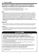
1. CAUTIONS This device complies with Part 15 of the FCC Rules. Operation is subject to the following two conditions: 1. This device may not cause harmful interference. 2. This device must accept any interference received, including interference that may cause undesired operation. Note This equipment has been tested and found to comply with the limits for a Class A digital device, pursuant to part 15 of the FCC Rules.
1. CAUTIONS WEEE (Waste Electrical & Electronic Equipment) This marking shown on the product or its literature, indicates that it should not be disposed with other household wastes at the end of its working life. To prevent possible harm to the environment or human health from uncontrolled waste disposal, please separate this from other types of wastes and recycle it responsibly to promote the sustainable reuse of material resources.
2. IMPORTANT SAFETY INSTRUCTIONS 1) Read these instructions. 2) Keep these instructions. 3) Heed all warnings. 4) Follow all instructions. 5) Do not use this apparatus near water. 6) Clean only with dry cloth. 7) Do not block any ventilation openings. Install in accordance with the manufacturer’s instructions. 8) Do not install near any heat sources such as radiators, heat registers, stoves, or other apparatuses (including amplifiers) that produce heat.
3.
4.
5. INSTALLATION 1. Attach the Camera to the ceiling with using the screws provided, taking into considering the camera angle required for the surveillance function. Template M4 Tappint Screw - 3EA 2. Adjust the LENS ANGLE to the desired location by hand.
5. INSTALLATION 3. Connect the VIDEO OUT CABLE and check the video image. Change the SETTINGS accordingly using the OSD controller. Controller Test Video Connector Video Output Test Cable 4. After the SETTING is completed, install the TOP COVER.
5. INSTALLATION • MONITOR CONNECTION - DC12V/AC24V DC12V/AC24V (TERMINAL BLOCK) DC12V/AC24V POWER SUPPLY MONITOR BNC FEMALE VIDEO IN CAMERA DC12V ADAPTER DC12V (DC JACK) - DC12V MONITOR BNC FEMALE VIDEO IN CAMERA When you install the camera, please glue the end of cable to keep it stable in order to protect the camera from humidity problems.
55 6.
7. SPECIFICATIONS Image Sensor Scanning System H Resolution. Scanning Frequency Total Pixels No. LED Type Standard Type 1/3” 960H SONY Double Scan Super HAD CCD II 2 : 1 Interlace 750TV Lines NTSC: 15.734KHz(H), 59.94Hz(V) / PAL: 15.625KHz(H), 50Hz(V) NTSC: 1028(H) X 508(V) / PAL: 1028(H) X 596(V) Effective Pixels No. NTSC: 976(H) X 494(V) / PAL: 976(H) X 582(V) S/N Ratio More than 50dB(3DNR ON) Min. Illumination Sync System Gamma 0Lux Video Output 1.
8. OSD MANUAL • Menu structure Main MENU 1st Sub MENU 2nd Sub MENU HIGH LUMINANCE AUTO EXPOSURE SHUT AGC RETURN SPEED ATW 4th Sub MENU FLICKERLESS BRIGHTNESS OFF / ON 0 ~ 255 OFF, AGC, SLOW, AGC->SLOW, SLOW->AGC, AGC->SLOW->AGC 6, 12, 18, 24, 30, 36 2, 4, 8, 16, 32, 64, 128, 256 x0.25,x0.50,x0.75,x1.
8.