Installation Guide 10Base-T Ethernet Hub Model: DH8T DOC.
KTI Networks Inc. All rights reserved. No part of this documentation may be reproduced in any form or by any means or used to make any directive work (such as translation or transformation) without permission from KTI Networks Inc. KTI Networks Inc. reserves the right to revise this documentation and to make changes in content from time to time without obligation on the part of KTI Networks Inc. to provide notification of such revision or change.
The information contained in this document is subject to change without prior notice. Copyright Ó KTI. All Rights Reserved. TRADEMARKS Ethernet is a registered trademark of Xerox Corp. NetWare is a registered trademark of Novell Inc. WARNING: This equipment has been tested and found to comply with the limits for a Class A digital device, pursuant to Part 15 of the FCC Rules.
10BASE-T ETHERNET HUB INSTALLATION GUIDE DOC.
Table of Contents Chapter 1 Introduction Introduction ............................................................................... 1 Features .................................................................................... 2 Chapter 2 Installation Installation ................................................................................. 3 Checking AC Power .................................................................. 3 Chapter 3 Making Network Connection Network Connectors ................
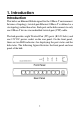
1. Introduction Introduction This hub is an Ethernet Hub designed for the 10Base-T environment. In terms of topology, twisted-pair Ethernet 10Base-T is defined as a star topology rather than a bus. Each port on the hub connects to only one 10Base-T device via unshielded twisted-pair (UTP) cable. The hub provides eight Twisted-Pair (TP) ports (RJ-45 Jacks) and one 12V DC power socket on the rear panel. On the front panel, there are ten LED indicators for displaying the port status and the hub status.
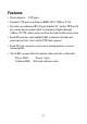
Features • Network ports: 8 TP ports • Standard: TP ports conform to IEEE 802.3 10Base-T std. • Provides an additional RJ-45 jack labeled '8C' on the TP Port #8 for connecting to another hub. A standard straight-through 10Base-T UTP cable can be used for the hub-to-hub connection. • Each TP port has one Link/Rx LED to indicate the link and receiving activity status of the UTP link segment. • Each TP port can detect and correct wiring polarity reversal automatically.
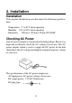
2. Installation Installation You can place the hub in an area that meets the following specifications: o o Temperature: 5 to 40 C when operating Humidity: 10% to 80% when operating Dimension: 195 mm x 129 mm x 28 mm (WxDxH) Checking AC Power One AC power adapter is contained in the hub package. Before you begin the installation, check the AC voltage of your area.
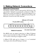
3. Making Network Connections Network Connectors The hub has 8 TP ports which are presented by 8 RJ-45 jacks. The jacks labeled 1 through 8 are permanently configured as 10Base-T MDI-X jacks and the jack labeled '8C' next the jack labeled '8' is an alternative jack which is configured as MDI jack for the TP port #8. Both jacks can not be used at the same time. The MDI-X jacks can support connections to 10Base-T Ethernet nodes or lower level hubs via 10Base-T UTP cables.
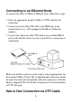
Connecting to an Ethernet Node To connect the hub to a 10Base-T Ethernet node, follow these steps: 1. Select an appropriate length of 10Base-T UTP cable for the connection. 2. Connect one end of the UTP cable to the MDI jack on the remote device (e.g., a PC equipped with 10Base-T Ethernet adapter). 3. Connect the other end of the UTP cable to an available MDI-X jack on the hub. It is better to reserve jack #8 for a connection to another hub.
When the number of 10Base-T nodes in your network exceeds eight, you need to connect at least two hubs to integrate all 10Base-T nodes into one network. You may connect one hub to another hub by using an ordinary UTP cable as the following steps: 1. Connect one end of the UTP cable to the jack labeled '8C' of Hub A. 2. Connect the other end of the cable to any available MDI-X jack of Hub B. The maximum length of the UTP cable connecting two hubs is 100 meters.
When connecting more than two hubs via TP ports and UTP cables, it is important to minimize the number of hubs in any path of the network. You may select one hub to serve as a primary hub to which other hubs will be connected. This will minimize the number of hubs in any path (node to node) on the network.
4. Interpreting Hub LEDs Locations of the Hub LED Indicators The hub provides the following LEDs : • One Power status LED • One Collision status LED • Eight Link and activity status LEDs. One for each TP port Interpretations Power LED The LED indicates the status of the hub's power source. Match the activity of the LED with one of the states indicated in the table. State Indication On Normal Off Problem Interpretation The power of the hub is on. No power is being supplied to the hub.
Collision LED This LED indicates the collision detected by the hub. The LED is normally off and it blinks when there are collisions. As the frequency of collisions on a network increases, the blink activities (on-time) of the LED also increase. Link/Rx LED Each TP port has one Link/Rx LED to indicate the link status and receiving activities of the connection to the attached device.
Appendix Specifications Temperature: Humidity: Dimension: o o Operating 5 to 40 C o o Storage -40 to 70 C Operating 10% to 80% Storage 5% to 90% 195mm (W) x 129mm (D) x 28mm (H) 7.7 inch (W) x 5.1 inch (D) x 1.1 inch (H) RJ-45 Jack Pin Assignments The following illustrations indicate the pin assignments of the RJ-45 jacks on the hub.
UTP Cabling Specifications The hub's TP ports support standard 10Base-T cable topologies and types, including Category 3, 4, or 5 unshielded twisted pair cable. The maximum length supported by the Ethernet is 100 meters of UTP cable. The cable, quality, distance, and connectors must comply with the EIA/TIA 568 'Commercial Building Wiring Standard'.