Modular Media Converter Center System KC-1300 Operation Manual DOC.
(C) 2005 KTI Networks Inc. All rights reserved. No part of this documentation may be reproduced in any form or by any means or used to make any directive work (such as translation or transformation) without permission from KTI Networks Inc. KTI Networks Inc. reserves the right to revise this documentation and to make changes in content from time to time without obligation on the part of KTI Networks Inc. to provide notification of such revision or change.
The information contained in this document is subject to change without prior notice. Copyright (C) KTI. All Rights Reserved. TRADEMARKS Ethernet is a registered trademark of Xerox Corp. WARNING: This equipment has been tested and found to comply with the limits for a Class A digital device, pursuant to Part 15 of the FCC Rules. These limits are designed to provide reasonable protection against harmful interference when the equipment is operated in a commercial environment.
Table of Contents 1. Introduction ......................................................... 6 1.1 Features ........................................................................................ 7 1.2 Technical Specifications ............................................................... 8 2. Installation ......................................................... 12 2.1 Unpacking .................................................................................... 2.2 System Units .........................
6.5.1 Basic ......................................................................................... 6.5.2 Console Port Information ......................................................... 6.5.3 Security Manager ...................................................................... 6.5.4 Image Refresh Time ................................................................ 6.5.5 Update Firmware ...................................................................... 6.5.6 Reboot System ........................
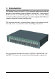
1. Introduction The Modular Converter System KC-1300 is a managed media converter rack that provides 16 slots and hosts 16 units of Media Converter (MC). A wide range of media converters are available depending on your variety of network cabling environment. These optional media converters include Gigabit and Fast Ethernet copper to multimode or single mode fiber cable. The rack unit provides a centered power supply to the converter modules and serves as a converter center and wiring concentrator.
1.
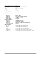
1.2 Technical Specifications System Model Management support Plug-in power modules Input voltage Power supply rating Weight (no MC installed) System Model Management support Plug-in power modules Input voltage Power supply rating Weight (no MC installed) KC-1300L/1A KC-1300L/2A KC-1300/1A KC-1300/2A Unmanaged 1 AC 90~264V 60W 5.5Kg KC-1300L/1D Managed 1 AC 90~264V 60W 5.5Kg Managed 2 AC 90~264V 60W 6.2Kg KC-1300L/2D KC-1300/1D KC-1300/2D Unmanaged 1 DC -48VDC 60W 5.
AC Power Chassis Module Specifications Dimension 194mm x 156.6mm x 40.3mm Installation method Plug in from system rear panel Maintenance Modular design for easy maintenance AC power switch System power on/off switch AC power receptacle IEC320 type receptacle Power status indicator Green LED Electric Input voltage rating 100 ~ 240VAC Input voltage range 90 ~ 264VAC Input frequency 47 ~ 63Hz Input surge current 20A max.
Management Module Specifications Dimension 107mm x 24mm x 86.4mm Slot position Slot 0 CPU RISC-based ARM7 RAM size 2M bytes Flash size 512K bytes System interface Connector FutureBus Console interface Interface RS-232 DTE Connector 9-pin male D-SUB connector Baud rate 38400, N, 8, 1, 0 Flow control Disabled In-band interface Interface 10/100M LAN port Connector Shielded RJ-45 MDI Standard IEEE 802.
Management Specifications Management interface Telnet Via direct RS-232 console connection Telnet Via TCP/IP Telnet software SNMP agent Via TCP/IP SNMP manager software HTTP server Via web browser software Protocols IPv4 IP version4 RFC791 TCP Transmission Control Protocol RFC793 UDP User Datagram Protocol RFC768 ICMP Internet Control Message Protocol RFC792 SNMP SNMP agent v1 RFC1157 MIB-II Standard MIB RFC1213 TFTP Trivial File Transfer Protocol RFC1350 TELNET Telnet protocol RFC854 HTTP HTTP server for w
2. Installation 2.1 Unpacking The product package contains: • The system unit • One power cord • One 19-inch rack mounting kit • Operation Manual 2.2 System Units The figure below illustrates the front view of the KC-1300 system: Depending on the model purchased, the type and numbers of the preinstalled media converters may be different. The figure shows a system which is fully installed with media converters. The following figures show the rear view of the KC-1300 system.
The following figure shows the model equipped with two AC power chassis. Main Chassis : provides insertion slots on front panel for CPU management module and optional add-on media converters. It also provides two chassis slots on rear for mounting power chassis modules. Management Module : serves as a management agent to monitor system status and add-on converter modules for in-band and out-of-band management requests. Power Chassis : provides full centered power supply for whole system unit.
2.2.2 Management Module The system unit comes with one pre-installed Management module.
Console Port This port is a 9-pin male D-sub connector. It serves as an RS-232 DTE port. Refer to Chapter xx for the console operation. The pin definitions are: Pin2 Pin 3 Pin 4 Pin 5 Pin 6 RXD TXD DTR GND DSR UTP Port This is an auto-negotiation 10/100BASE-TX LAN port and provides a shielded RJ-45 jack with MDI definition. This port must connect to your TCP/IP network for all in-band management operations.
2.2.3 Power Chassis Modules The system power supply is assembled in a plug-in chassis module as shown below: Each single power module is capable to supply full power for system operation with media converters fully installed.
DC Power Chassis Specifications (KC1300-DC) Input power switch System power on/off switch Input power receptacle Terminal connector (screw type) Input voltage rating -48VDC Input voltage range -48VDC +/-10% Output power 60W Power status display Green LED -17-
Removal of System Power Chassis The system power chassis is pre-installed in the system unit when system unit is shipped from factory. The chassis is designed for easy uninstallation from system unit in case of any inspection purpose. However, note that this removal only can be performed by a well-trained technical person. For safety reason before removing the power chassis, make sure: • The power switch is turned off. • The power cord is disconnected from the power chassis.
Insertion of System Power Chassis Before inserting the power chassis into system unit, make sure: • The system power switch is turned off. • The power cord is disconnected from the power chassis. To insert the power chassis, hold the handle and push it into system unit until it is seated in system chassis properly. Screw the chassis securely in the system unit.
2.2.4 Media Converter Slots The system chassis provides sixteen slots for installing optional slide-in MCs. A media converter can be inserted into an available slot or removed from a slot anytime even when system unit is powered on. This hot-plug design keeps all exiting connections on the other slots running with no influence. To insert an MC into a slot, the steps are: 1. Install a bracket, which is provided in the rack chassis package onto the MC unit as shown below: 2.
To remove an MC from slot, the steps are: 1. Disconnect all cable connections on the MC first. 2. Unscrew the MC bracket from system chassis. 3. Hold the bracket and pull it slowly out from the slot. The media converters are designed with hot-plug feature, which allows insertion and removal of the converters can be performed even when the system is in operation.
2.3 Rack Mounting One rack mounting kit is supplied in the product package. It includes two rack mounting brackets and screws for installing the system unit into a 19-inch rack.
3. Network Management 3.
The system unit is equipped with one management module which serves as a management agent to monitor the system status and all installed media converter modules. The agent also responses to either in-band management requests coming from network or out-of-band requests from directly connected console. 3.
3.3 Setup for Out-of-band (Console) Management Before doing any in-band management, it is necessary to perform console operation for configuring IP and SNMP related settings for the first time the system is received for installation. The console port is located on the SNMP module. Any PC running Windows can be used as a console via COM port. Windows Hyper Terminal program is an ideal and the most popular software for such console terminal operations. To setup console operation, the steps are: 1.
2. Connect one end to the console port and connect the other end to the PC COM port. 3. Configure your PC COM port setting to match the RS-232 settings of the console port and start your terminal software. Factory default settings of the Console port Baud rate : 38400, N, 8, 1, 0 Flow control : disabled 4. Turn the system power on. 5. Press key several times in your terminal software until a login prompt comes up. It means the connection is proper.
3.4 Setup for In-band Management To perform an in-band management, it is necessary to connect the system to your TCP/IP network. The steps are: 1. Configure IP and SNMP related settings to the system using direct console management when you receive it first time for the installation. 2. Find a proper straight-through Category 5 UTP cable (maximal length 100 meters) for the connection. 3.
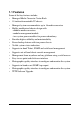
4. Console and Telnet Operation Functions supported: • Set and display IP parameters for the system. • Set and display SNMP parameters for the SNMP agent function. • Monitor system power status, power temperature status, system fan status and other system information. • Monitor installation status of each slots. • Monitor the configuration and link status of each MC installed. • Restore default settings for the system • Change administrator password for access control. • Update system software.
* Remote MC TP link status monitoring is available only when KC300DM in the rack is connected to a remote KC-300DM through fiber link. Cold Start When the power to the system is turned on, the system start initialization and self-test process. The self-test messages are displayed as follows if a console connection is established successfully.: Power-on Self-test --------------------------------------------$$$ System LOADER Checksum O.K !!! $$$ System IMAGE Checksum O.K !!! $$$ System DATA Checksum O.
Direct Console Management When you can see the self-test messages shown on screen properly, you can press key to start console login operation. Go to Login Prompt section in next page directly. Telnet Management Use Telnet software to perform the management operation. The most convenient solution is using the built-in Telnet function in a Windows 95/98/ or NT PC. Enter into DOS window and invoke Telnet command : >telnet xxx.xxx.xxx.xxx to connect to the system unit. The specified xxx.xxx.xxx.
When login successfully, a Setup menu is shown as follows: --------------------------------------------Setup Menu TCP/IP stack for KC-1300 V1.xx [0] Print this menu [1] IP Menu [2] SNMP Menu [3] View System status [4] View Converter Slots Status [5] Restore Default Value [6] Security Manager [7] Update Firmware [8] Reboot System [9] Exit Please Select (0-9 ).... Enter Esc to abort....
4.1 IP Menu Select [1] from Setup menu to set IP related settings. --------------------------------------------IP Menu [0] Print this menu [1] Set IP Address [2] View IP Status [3] Exit Please Select (0-3) --------------------------------------------- Set IP Address ---------------------------------------------------------------------Enter ESC to abort. Please Input IP Address(xxx.xxx.xxx.xxx):192.168.0.23 replacing net[0] IP address nnn.nnn.nnn.nnn with 192.168.0.23 Please Input Subnet Mask(xxx.xxx.xxx.
4.2 SNMP Menu Select [2] from Setup menu to perform SNMP related settings. The following figure illustrates the SNMP menu: --------------------------------------------Snmp Menu [0] Print this menu [1] View Snmp Setting [2] Set Snmp Name [3] Set Snmp Location [4] Set Snmp Contact [5] Set Snmp Community [6] Set Snmp Trap Manager [7] Exit Please Select (0-7 )....
4.3 View System Status Select [3] from Setup menu to view system status. The system status are shown as follows: --------------------------------------------Power 1 Status: Good , Power 2 Status: Good FAN status: Good CPU status: Cpu Type = ARM7, Flash Size = 512K, Sdram Size = 2M Bytes Software version 1.xx --------------------------------------------- Power status indicates the status of system power 1&2 chassis. Power Status : Good, Bad FAN status indicates the status of system cooling fan.
4.4 View Converter Slots Status Select [4] from setup menu to view current status of all media converter modules in the system.
The slot status definitions are: Column Slot States 01-16 Interpretation Slot position in the system Slot #1 - slot #16 are for MC Port N/A A B No module is installed in slot Upper port of the module in slot Lower port of the module in slot Media N/A TX T FX X No MC is installed in slot.
4.5 Restore Default Values Select [5] from Setup menu to restore factory default settings. Factory default settings are: IP Address 192.168.0.2 Subnet Mask 255.255.255.0 Default Gateway 192.168.0.1 User Name admin Password 123 Name (null) Location (null) Contact (null) SNMP Communities: No.1 Community name public No.1 Access right Read only No.2 Community name (null) No.2 Access right (N/A) No.3 Community name (null) No.3 Access right (N/A) No.4 Community name (null) No.
4.6 Security Manager Select [6] from Setup menu to change login user name and password. The steps are: Display current user name --------------------------------------------Current username: admin Current password: ******** Press Esc to abort .... --------------------------------------------- Change user name and password --------------------------------------------Change username [admin]: xxxxxx Enter password(1-8): ******** Confirm password: ******** Password updating ....... Password updated.
4.7 Update Firmware Select [7] from Setup menu to perform firmware (system software) upgrade via TFTP protocol. Before doing TFTP operation, one TFTP server is required and installed in the network to where this system connects and new firmware file image.bin must be placed in the TFTP server. The following information are required for TFTP operations: TFTP Server IP Address: IP address of the TFTP server where the firmware image.bin is downloaded from.
The steps are: Specify TFTP server IP address --------------------------------------------Enter ESC to abort. Please Input TFTP Server IP Address (xxx.xxx.xxx.xxx):192.168.0.88 TFTP Server: 192.168.0.88 --------------------------------------------- Confirm to start downloading --------------------------------------------Do you want to start download new image ? (Y/N) Y Download image and please wait........
5. SNMP Management SNMP management are performed at a network management station running SNMP network management application manager software with graphical user interface. The following figure illustrates an example model: The system unit serves as an SNMP agent and provides the capabilities that allows network administrators via SNMP protocol to set parameters and view system status and media converter status defined in the standard MIB-II and private MIB.
5.1 Configuring SNMP Settings via Console Operation Before performing SNMP operation, proper SNMP settings must be configured in the system unit.
5.2 SNMP Private MIB Use the SNMP management application software to compile the MIB file first before performing any management operation. In addition to standard MIB-II (RFC1213), the system supports private MIB as below: Private MIB Objects ssPowerStatus(kti.30.1.1) ssFanStatus(kti.30.1.2) cputype(kti.30.2.1) flashrom(kti.30.2.2) memsize(kti.30.2.3) softwarever(kti.30.2.4) mibFileVer(kti.30.2.5) portNumber(kti.30.3.1) portTable(kti.30.3.
5.3 SNMP Traps The system also supports the following SNMP traps. When the trap event occurs, the SNMP agent will generate a trap notification to SNMP management station.
6. Web Management The system features an http server which can serve the management requests coming from any web browser software over internet or intranet network. Web Browser Compatible web browser software with JAVA support Microsoft Internet Explorer 4.0 or later Netscape Communicator 4.x or later Set IP Address for the System Unit Before the system can be managed from a web browser software, make sure a unique IP address is configured to the system. Refer to Chapter 4 for how to set IP address. 6.
6.
The following screen shows welcome screen when a successful login is performed. In addition to the device image, the screen supports the following functions on the right side: 1. 2. 3. 4.
6.3 Converter Status Click [Converter Status] to view all slot status in a table list.
The information includes: Column Slot States 1-16 Interpretation Slot position in the system Slot #1 - slot #16 are for MC installation Port A B Upper port of the MC in slot Lower port of the MC in slot Media TX T FX X 10/100BASE-TX copper port type 1000BASE-T copper port type 100BASE-FX Optic fiber port type 1000BASE-X Optic fiber port type Link Green Red Link up Link down Speed 10Mbps 10BASE-T 100Mbps 100BASE-TX or 100BASE-FX 1000Mbps 1000BASE-T or 1000BASE-SX/LX Duplex Full Half RTP link
6.4 System Status Click [System Status] to view system related status in a table list.
6.5 Administrator Menu Click [Administrator] to show administrator menu. The menu includes the following options: 1. Basic : Set / View IP and SNMP related settings 2. Console Port Information : View RS-232 console configuration 3. Security Manager : Change login user name and password 4. Image Refresh Time : Set refresh time interval of the image 5. Update Firmware : Update the software built in SNMP module 6. Reboot System : Reboot the system remotely Refer to the following sections for the details.
6.5.1 Basic Click [Basic] to perform IP setting and SNMP settings. IP setting and SNMP setting are described in the following sections respectively.
Click [IP Address] button to set IP settings. IP settings include: IP Address Subnet Mask Gateway : Unique IP address designated to this system : The subnet mask of the IP address specified above : The IP address of the default gateway (router) Click [Update Settings] to make new settings effective. However, a new IP address change will make your current connection invalid. Restart your web link with new IP address to connect the system.
Click [SNMP Entries] button to set SNMP settings.
SNMP Entries - Community Strings One community contains two settings: Community name : SNMP communities to which the system belongs Access right : Access right associated with the community name Click [Add] button to add one new community into the community list. Click [Remove] button to remove one community from the community list. Up to four entries are supported in the community list.
SNMP Entries - Trap Managers One Trap Manager contains two settings: IP Address : IP address of the trap host to which a trap is issued Community : The trap community to which the system belongs Enable Fan Trap: Enable trap for Fan failure events Enable Power Trap: Enable trap for power failure events Enable Link Change Trap: Enable trap for any link change events Click [Add] to add one trap manager into the manager list. Click [Remove] to remove one trap manager from the manager list.
6.5.2 Console Port Information This screen displays configuration of RS-232 console port.
6.5.3 Security Manager Security Manager allows you to change login user name and password. Click [Apply] to make the changes effective.
6.5.4 Image Refresh Time The system image is updated periodically to present the latest status. The default time interval of refreshing the image is 20 seconds. It can be changed by clicking any of the time buttons displayed. This is a run time setting and not a permanent setting.
6.5.5 Update Firmware [Update Firmware] allows you to perform firmware (system software) upgrade via TFTP protocol. Before doing TFTP operation, one TFTP server is required and installed in the network to where this system connects and new firmware file image.bin must be placed in the TFTP server. Set IP address for the TFTP server from where the firmware image is to be downloaded. Specify the file name as Image.bin. Click [Apply] to start the file transfer operation.
6.5.6 Reboot System [Reboot System] allows you to reboot the system unit remotely. Starting this command will make your current http connection lost. You must rebuild the connection to perform any management operation to the unit.
6.6 Slot Icon Operations In addition to the menu supported, you may click the following image icons to show specific status.
Click any one slot in slot 1 to slot 18 to view one specific slot status. The following figure illustrates slot 9 status: Refer to section 6.3 for status interpretation.