INDUSTRIAL 1000BASE-T TO 1000BASE-X MEDIA CONVERTERS KCD-400 Series Installation Guide DOC.
(C) 2005 KTI Networks Inc. All rights reserved. No part of this documentation may be reproduced in any form or by any means or used to make any directive work (such as translation or transformation) without permission from KTI Networks Inc. KTI Networks Inc. reserves the right to revise this documentation and to make changes in content from time to time without obligation on the part of KTI Networks Inc. to provide notification of such revision or change.
The information contained in this document is subject to change without prior notice. Copyright (C) All Rights Reserved. TRADEMARKS Ethernet is a registered trademark of Xerox Corp. FCC NOTICE This device complies with Class B Part 15 the FCC Rules. Operation is subject to the following two conditions: (1) This device may not cause harmful interference, and (2) this device must accept any interference received including the interference that may cause.
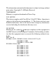
Table of Contents 1. Introduction ......................................................... 5 1.1 Features ........................................................................................ 6 1.2 Specifications ................................................................................ 7 1.3 Special Functions ......................................................................... 11 2. Installation ......................................................... 13 2.1 2.2 2.3 2.4 2.5 2.6 2.7 2.
1. Introduction The industrial 1000BASE-T to 1000BASE-X media converter series provides industrial strength Ethernet copper-to-fiber media conversion, allowing for 1000Base-T-to-1000Base-X over multi-mode or optional singlemode fiber optical media.
1.1 Features • • • • • • • • • • • • • • • • • • Gigabit copper to fiber conversion: 1000Base-T-to-1000Base-SX/LX over multimode or single-mode fiber SFP design : For flexibility, an SFP (Mini-GBIC) connector is provided for the fiber port to accommodate any type of SFP fiber transceiver when needed.
1.
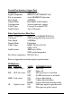
Twisted-Pair Interface (Copper Port) Connector Shielded RJ-45 Signal Compliance IEEE 802.3ab 1000BASE-T std. Pin Assignments Auto MDI/MDI-X detection Data Speed 1000Mbps Duplex Mode Half-duplex or Full-duplex Configuration Auto-negotiation support Cable Types Category 5 or higher UTP Link Distance Up to 100 meters Fiber Optic Interface (Fiber Port) Signal Compliance IEEE 802.3z 1000BASE-SX/LX std.
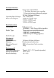
DC Power Interface Interface Operating Input Voltages Power consumption Basic Information Conversion Screw-type terminal block 1. Two pairs for power wire cascading 2. One pair for power failure relay output DC Jack (-D6.3mm/+D2.0mm) +7V ~ +30V(+5%) 2.25W @+7.5VDC input 2.3W @+24VDC input 2.5W @+30VDC input Packet Length Full wire speed 1000Mbps - 1,488,00pps at 64-byte packets Transparent and no modification for - IEEE 802.3 standard packets - IEEE 802.
Certificate FCC CE/EMC CE/LVD Safety Part 15 Class B EMI EN50081-1 Class B EMS EN55024 EN 60950 EN 50081-1/1992 : EN55022:1994/A1:1995/A2:1997 EN61000-3-2:2000 EN61000-3-3:1995/A1:2001 EN 55024:1998/A1:2001 IEC 61000-4-2:1995 ESD Test IEC 61000-4-3:1995 RS Test IEC 61000-4-4:1995 EFT/BURST Test IEC 61000-4-5:1995 Surge Test IEC 61000-4-6:1996 CS Test IEC 61000-4-8:1993 Magnetic Field IEC 61000-4-11:1994 Volatge Int.
1.3 Special Functions Auto MDI/MDI-X Function This function allows the copper port to auto-detect the twisted-pair signals and adapts itself to form a valid MDI to MDI-X connection with the remote connected device automatically. Link Fault Pass Through Function When a link fault is detected on the copper port, the device will force a link down on the fiber port immediately. Similarly, a link fault detected on the fiber port will also force a link down on the copper port.
Far End Fault Function The fiber port is facilitated with this function. When the fiber port detects a link failure on its receiving circuitry, it will send out an FEFI (Far End Fault Indication) signal to the remote connected device to indicate a remote fault is detected. It also is capable to receive FEFI signal sent from the remote link partner if the link partner detected a receiving fault. Upon receiving an FEFI signal, it indicates a link failure occurred on the transmitting path.
2. Installation 2.1 Unpacking Check that the following components have been included: • Information CD • The Media Converter unit • DIN-rail mounting bracket If any item is found missing or damaged, please contact your local reseller for replacement. The following are available optional accessories: • Panel Mounting Bracket • The bracket is used for mounting the converter on a panel surface. Commercial-rated AC power adapters: - Rated AC120V/60Hz DC7.5V 1A - Rated AC230V/50Hz DC7.
2.2 Safety Cautions To reduce the risk of bodily injury, electrical shock, fire, and damage to the equipment, observe the following precautions. • Do not service any product except as explained in your system documentation. • Opening or removing covers may expose you to electrical shock. Only a trained service technician should service components inside these compartments.
2.3 DIN-Rail Mounting In the product package, a DIN-rail bracket is installed on the device for mounting the converter in a industrial DIN-rail enclosure. The steps to mount the device onto a DIN rail are: 1. Install the mounting bracket onto the device unit as shown below: 2. Attach bracket to the lower edge of the DIN rail and push the unit upward a little bit until the bracket can clamp on the upper edge of the DIN rail. 3. Clamp the unit to the DIN rail and make sure it is mounted securely. 4.
The final mechanical dimensions after installing DIN rail mounting bracket are: -16-
2.4 Panel Mounting The device is provided with an optional panel mounting bracket. The bracket support mounting the device on a plane surface securely. The mounting steps are: 1. Install the mounting bracket on the device unit. 2. Screw the bracket on the device unit. 3. Screw the device unit on a panel. 4. Make sure that there are proper heat dissipation from and adequate ventilation around the device. Do not place heavy objects on the device.
The screw locations and final dimension are shown below: -18-
2.5 Applying Power The power specifications of the device are: Operating Voltage +7 ~ +30VDC Power Consumption Max. 2.5W @30VDC The device provides two types of power interfaces, terminal block and DC power jack for receiving DC power input from external power supply. Using Terminal Blocks Either DC1 interface or DC2 interface can be used to receive DC power from an external power system. Or, DC2 also can be used to deliver the power received on DC1 to next device in cascading way.
Power wires: 24 ~ 12AWG (IEC 0.5~2.5mm2) Install the power source wires with the plug properly. Screw the wire with plug securely. Then, plug in DC1 contacts. If cascading the power to next device is needed, install the power wires and plug for another switch. Then, use DC2 contacts. Note: Only up to four device units can be cascaded to receive power from one main power input source.
Using DC Power Jack DC Jack Connector: Jack D 6.3mm D 2.0mm AC Power Adapters: Optional commercial rated adapters are available for purchasing. Rated AC120V/60Hz DC7.5V 1A Rated AC230V/50Hz DC7.5V 1A Rated AC100V/50-60Hz DC7.5V 1A Rated AC240V/50Hz DC7.5V 1A Connect power adapter DC plug to the DC power jack of the converter before connecting to the AC outlet. Connect the power adapter to the AC outlet. Note: Before you begin the installation, check the AC voltage of your area.
2.6 Power Failure Relay Output The device provides a relay output to report power failure event to a remote alarm monitoring system. The replay output is provided with two contacts labeled PF+ and PF- in the terminal block interface. Use the provided 2P terminal plug for signal wiring and plug into the PF+/ - contacts. The function is designed as : Power is normal PF+ contact is shorted with PF- contact. Power failure PF+ contact is disconnected with PF- contact.
2.7 Making Twisted Pair Copper Port Connection Copper port is featured to support connection to : • Auto-negotiation devices • Auto-negotiation incapable 10BASE-T devices • Auto-negotiation incapable 100BASE-TX devices Network Cables 1000BASE-T: 4-pair UTP Cat. 5e or 6, EIA/TIA-568B 100-ohm STP Link distance: Up to 100 meters Note: The copper port is featured with auto MDI/MDI-X crossover detection and configuration function.
2.8 Making Fiber Port Connection The mini-GBIC (SFP) port must be installed with an SFP fiber transceiver for making fiber connection. The device may come with an SFP transceiver pre-installed when it is shipped from factory. Installing SFP Fiber Transceiver Turn off the power to the device. Insert the SFP fiber transceiver into the mini-GBIC port. Normally, a bail is provided for every SFP transceiver. Hold the bail and make insertion.
3 LED Indicators The following figure shows the locations of the configuration switches and LED indicators: 3.1 LED Indicators LED DISPLAY PWR Power status STATE ON OFF INTERPRETATION The device is powered on. The device is powered off. SFP ON OFF An SFP transceiver is installed. No SFP transceiver is installed.
Appendix: Model Optical Specifications The media converter series provides the following fiber options: Model Specifications KCD-400-xx FX Reference Fiber Distance Wavelength Operating Temperature -SX LC 850nm 50/125 MMF 500m -20 ~ 70oC 62.5/125 MMF 200m -LX LC 1310nm MMF 550m SMF 10km -20 ~ 70oC -LX20 LC 1310nm SMF 20km -20 ~ 70oC Optical Specifications KCD-400-xxx FX Tx Power Sensitivity -SX LC -9.5 ~ -4 dBm -18dBm Max. Rx Power -1 dBm -LX LC -9.