KGC-310 / KGC-310M Web Smart Gigabit Ethernet Media Converter Installation Guide DOC.
(C) 2005 KTI Networks Inc. All rights reserved. No part of this documentation may be reproduced in any form or by any means or used to make any directive work (such as translation or transformation) without permission from KTI Networks Inc. KTI Networks Inc. reserves the right to revise this documentation and to make changes in content from time to time without obligation on the part of KTI Networks Inc. to provide notification of such revision or change.
The information contained in this document is subject to change without prior notice. Copyright (C). All Rights Reserved. TRADEMARKS Ethernet is a registered trademark of Xerox Corp. WARNING: This equipment has been tested and found to comply with the limits for a Class A digital device, pursuant to Part 15 of the FCC Rules. These limits are designed to provide reasonable protection against harmful interference when the equipment is operated in a commercial environment.
Table of Contents 1. Introduction .................................................................................................. 6 1.1 Features ................................................................................................................... 7 1.2 Product Panels ......................................................................................................... 8 1.3 Specifications ....................................................................................................
4.8 Reboot System ....................................................................................................... 40 4.9 Restore Default ....................................................................................................... 40 4.10 Update Firmware ................................................................................................... 41 4.11 Logout ....................................................................................................................
1.
Quality of Service For conversion between two different speeds, the device is featured with powerful Quality of Service (QoS) function which can classify the priority for received network frames based on the ingress port and frame contents. Furthermore, many service priority policies can be configured for egress operation.
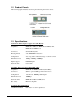
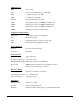
1.2 Product Panels The following figure illustrates the front panel and rear panel of the device: 1.3 Specifications 10/100/1000 Twisted-pair Copper Port (TP, RJ-45) Compliance IEEE 802.3 10Base-T, IEEE 802.3u 100Base-TX, IEEE 802.3u 1000Base-T Connectors Shielded RJ-45 jacks Pin assignments Auto MDI/MDI-X detection Configuration Auto-negotiation, manual settings or software control Transmission rate 10Mbps, 100Mbps, 1000Mbps Duplex support Full/Half duplex Network cable Cat.
LED Indicators PWR Power status LTP Local or remote TP indication on TP LEDs LBT Loopback test in-progress LED LBR Loopback test result LED FXLNK Fiber port link and activity status TP1G Twisted-pair copper port 1000Mbps and link status TP100 Twisted-pair copper port 100Mbps and link status TP10 Twisted-pair copper port 10Mbps and link status TPFDX Twisted-pair copper port duplex status Configuration DIP Switches SW1-SW3 Twisted-pair copper port configuration SW4 Flow control setting S
Environmental Operating Temperature Typical -5oC ~ 55oC Storage Temperature -20oC ~ 85oC Relative Humidity 10% ~ 90% Electrical Approvals FCC Part 15 rule Class A CE EMC, CISPR22 Class A Software Management Functions Interfaces Web browser Management objects System configuration - IP settings, Name, Password Port configuration control and status 802.
2. Installation 2.1 Unpacking The product package contains: • The media converter unit • One product CD-ROM 2.2 Safety Cautions To reduce the risk of bodily injury, electrical shock, fire, and damage to the product, observe the following precautions. • Do not service any product except as explained in your system documentation. • Opening or removing covers may expose you to electrical shock. • Only a trained service technician should service components inside these compartments.
2.3 Mounting the Media Converter The media converter can be mounted on a desktop or shelf or a wall. Make sure that there is proper heat dissipation from and adequate ventilation around the device. Do not place heavy objects on the device. Desktop mounting Wall mounting The device has one mounting wall on the bottom side to support wall mounting. Din-Rail mounting For a Din-Rail chassis, the device can support mounting on a Din-Rail. An optional Din-Rail bracket, KC-3DR can be purchased separately.
Center rack mounting The media converter can also be installed in KC-1300 center chassis. The center chassis provides the power supply to the converter also with optional power redundancy. Up to 16 units can be installed in one chassis. Unscrew and remove the cover of the center connector before inserting the converter into the chassis. Refer to the operation manual of center chassis KC-1300 for more information. 2.4 Applying Power Before you begin the installation, check the AC voltage of your area.
2.5 Making UTP Connections The 10/100/1000 twisted-pair copper (TP) port supports the following connection types and distances: Network Cables 10BASE-T: 2-pair UTP Cat. 3,4,5 , EIA/TIA-568B 100-ohm 100BASE-TX: 2-pair UTP Cat. 5, EIA/TIA-568B 100-ohm 1000BASE-T: 4-pair UTP Cat. 5 or higher (Cat.
2.6 Making Fiber Connection The mini-GBIC SFP (FX) port must be installed with an SFP fiber transceiver for making fiber connection. Your device unit may come with an SFP transceiver pre-installed when it is shipped. Installing SFP Fiber Transceiver To install an SFP fiber transceiver into mini-GBIC SFP port, the steps are: 1. Turn off the power to the device unit. 2. Insert the SFP fiber transceiver into the mini-GBIC port. Normally, a bail is provided for every SFP transceiver.
2.7 Loopback Test Push Button The push button is used to perform loopback test between two media converters connected with fiber cable as shown below: It allows installer to perform diagnostic to the fiber link during installation and check the test result displayed on the LED indicators. The button may also be used to restore the software configuration settings to factory default values.
2.8 Configuration DIP SW The configuration DIP SW (switches) are used for setting operation configuration manually.
2.9 LED Indication LED Function State Interpretation PWR Power status ON OFF The power is supplied to the unit. The power is not supplied to the unit. LTP Local TP status ON OFF Blink Local TP port status displayed on TPxxx LEDs Remote TP port status displayed on TPxxx LEDs Fail to display remote TP port status Remark: 1. LTP is always ON if remote TP status auto-report function is disabled. 2.
2.10 Configuring IP Address and Password for the Device For managed model, the device unit is shipped with the following factory default settings for software management : Default IP address of the device : 192.168.0.2 / 255.255.255.0 The IP Address is an identification of the device unit in a TCP/IP network. Each unit should be designated a new and unique IP address in the network. Refer to Web management interface for System Configuration.
3. Functions To help a better understanding about the software management interfaces, this chapter describes some advanced functions provided by the media converter. 3.1 Abbreviation TP Port : The twisted-pair copper port of the media converter device. FX Port : The optical fiber port of the media converter device. Ingress Port : Ingress port is the input port on which a packet is received. Egress Port : Egress port is the output port from which a packet is sent out. IEEE 802.
3.3 Link Fault Pass Through Function Description When the Link Fault Pass Through (LFPT) function is enabled and the media converter detects a link fault on one port segment, it will force the other port segment link down. It looks like that a link fault is passed from one port to the other. The following example illustrates a link fault occurs on the fiber cable (any one cable in a duplex fiber connection).
3.4 Remote TP Status Monitoring Function Description The local media converter can monitor the TP port link status of its remote link partner connected on the fiber cable. The status are displayed on the local LED indicators as follows: Methods to enable the function Hardware setting: DIP SW5 is set to ON position Software setting: Web management -> Configuration -> System -> [Remote TP auto report] Remote TP Status Display 1.
3.5 802.1Q Control Function 802.1Q Control function allows to perform 802.1Q VLAN related operation to the packets passing through the media converter according packet contents as follows: [Ingress Drop] setting The setting is the first filtering mechanism to filter all incoming untagged packets or to filter all incoming VLAN-tagged packets. The options are: Disable - Disable port ingress drop function Untag Only - All incoming untagged packets and priority-tagged packets are dropped.
[Default Tag -VID], [Default Tag - CFI], [Default Tag - Priority] settings These settings compose one ingress port Default Tag. This tag is used when a tag insertion is required for untagged packets. 802.1Q Filtering 802.1Q VID Filtering function allows to admit or reject certain VID tagged packets. Up to 16 allowed (positive list) or rejected (negative list) VIDs can be configured. This function allows to limit certain packets to pass from one link segment to another one. [VID Table] options Disable 802.
3.6 QoS Function The device provides a powerful Quality of Service (QoS) function to guide the packet forwarding in four priority classes. The versatile classification methods can meet most of the application needs. The function is useful for guiding the incoming traffic on high data rate port into low data rate port in priority.
3.6.1 Packet Priority Classification Each received packet is examined and classified into one of four priority classes, Class 3, Class 2, Class 1 and Class 0 upon reception. The device provides the following classification methods: 802.1p classification : use User Priority tag value in the received IEEE 802.1Q packet to map to one priority class DSCP classification : use DSCP value in the received IP packet to map to one priority class Port-based classification : used when 802.
3.7 SNMP Trap Function SNMP trap function allows the device to send trap message to an SNMP trap host over SNMP protocol when the associated trap event occurs. SNMP Trap settings The settings are used to configure a trap host who can receive the SNMP trap message issued from a media converter device unit.
4. Web Management The media converter features an http server which can serve the management requests coming from any web browser software over TCP/IP network. Web Browser Compatible web browser software with JAVA script support Microsoft Internet Explorer 4.0 or later Netscape Communicator 4.x or later Set IP Address for the System Unit Before the device unit can be managed from a web browser software, make sure a unique IP address is configured for the unit. 4.
4.3 Main Management Menu The following information describes the basic functions of the main menu.
4.4 System Configuration Description MAC Address The MAC address factory configured for the unit It can not be changed in any cases.
SNMP Trap SNMP trap function configuration Disable - the device is disable to send SNMP trap messages. Enable - the device is enable to send SNMP trap messages. Community Name Set community string to be bound with trap packets Trap IP Address Set IP address of the SNMP trap host 802.1Q Control 802.1Q Control function main configuration Disable - all packets are allowed to pass with no 802.1Q control. Enable - 802.1Q control mechanism is activated for the conversion.
4.4.1 Management VLAN Management VLAN settings allow administrator to access the device and perform the web management over a dedicated VLAN only. The following rules are applied with the Management VLAN: 1. If the 802.1Q Control function is disabled, Management VLAN settings are ignored and no VLAN limitation is applied in accessing the web management interface. The http server only accepts untagged management packets and replies untagged packets to the management host. 2.
4.5 Ports Ports Configuration has three major parts as follows: Port Configuration Port link status, port operating mode, port flow control 802.1Q Control 802.
Port Configuration Function Port TP - Twisted-Pair copper port FX - Fiber port Link Port link status Speed and duplex status with green background - port is link on Down with red background - port is link down Mode Select port operating mode Disabled - disable the port operation TP Mode Disable Auto 10 Half 10 Full 100 Half 100 Full 1000 Full Auto-negotiation Speed capability Disable port operation Enable 10, 100, 1000M Disable 10M Disable 10M Disable 100M Disable 100M Enable 1000M FX Mode Disable
QoS Control Description QoS 802.1p 802.1p priority classification Enable - set to enable this classification to the port for priority-tagged and VLAN-tagged packets Disable - 802.1p classification is not applied to the port QoS DSCP DSCP classification Enable - set to enable DSCP classification to the port for IP packets Disable - DSCP classification is not applied to the port. QoS Default Priority Default priority class, it is used when 802.1p and DSCP classifications are disabled.
4.5.1 802.1Q Filtering Configuration Description VID TABLE Specify the characteristic of the VID table. Disable - set to disable 802.1Q filtering function. Allowed VID - the VID table specifies the allowed VIDs rejected VID - the VID table specifies the rejected VIDs No. Entry of VID table - up to 16 VIDs can be configured in VID table VID 1 ~ 4095 - decimal 12-bit VID value [Apply] Click to apply the configuration change. [Refresh] Click to refresh current configuration.
4.5.2 802.1p Mapping Configuration Description Port TP - Twisted-Pair copper port FX - Fiber port tag m 3-bit User priority tag value m ( range : 0 ~ 7 ) Priority class Mapped priority class for tag m on Port Class 3 ~ Class 0 [Apply] Click to apply the configuration change [Refresh] Click to refresh current configuration [Close] Click to close the window Notes: 1. Each port has its own 802.1p mapping table. 2. The ingress port table is referred in 802.
4.5.
4.
4.7 Loopback Test This menu is used to start a loopback test operation with the link partner unit over the fiber link. The message displayed during test is: The result message displayed after a test finished is: The test result is also displayed on LEDs - LBT and LBR. 4.8 Reboot System This menu is used to reboot the device unit remotely with current configuration. Starting this menu will make your current http connection lost.
4.10 Update Firmware This menu is used to perform in-band firmware (software) upgrade. Enter the path and file name of new firmware image file for uploading. Configuration Description Filename Path and filename (warp format) [Browse] Click to browse your computer file system for the firmware image file [Upload] Click to start upload 4.11 Logout This menu is used to perform a logout from the web management.
Appendix A. Factory Default Settings Configuration DIP SW Unmanaged Model Managed Model SW3 SW2 SW1 ON ON ON OFF OFF OFF Auto,10/100/100,Full/Half Web configuration (SW4-6 ignored) SW4 OFF (Enable flow control) OFF SW5 OFF (Disable remote TP auto report) OFF SW6 OFF (Disable link fault pass through) OFF System Configuration Management VLAN - VID 0 Management VLAN - CFI 0 Management VLAN - User priority 0 IP Address 192.168.0.2 IP Subnet mask 255.255.255.0 Gateway IP 192.168.0.
Ingress Keep Tag Enable Egress Insert Tag Disable Default Tag - VID (PVID) 1 Default Tag - CFI 0 Default Tag - Priority 0 QoS 802.1p Disable QoS DSCP Disable QoS Default Priority Class 3 QoS Egress Service Strict priority 802.1Q Filtering VID TABLE Disable VID n (n=1-16) n 802.
Appendix B. Models & Optical Specifications Model Definition KGC-310 KGC-310-xxxx KGC-310M KGC-310M-xxxx Model Ext. -SX -LX -LX20 -LX30 -LX50 -LX70 Unmanaged model with no pre-installed SFP transceiver Unmanaged model with pre-installed SFP transceiver Managed model with no pre-installed SFP transceiver Managed model with pre-installed SFP transceiver FiberCon. LC LC LC LC LC LC Reference Fiber Distance (Typ.