
User`s manual

12
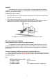
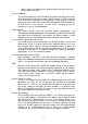
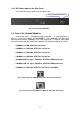
1-4. View of SW24GF
Fig. 1-1 Full View of SW24GF
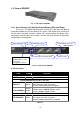
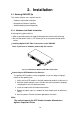
1-4-1. User Interfaces on the Front Panel (Button, LEDs and Plugs)
There are 8 TP Gigabit Ethernet ports and 24 SFP fiber ports for optional
removable modules on the front panel of the switch. LED display area, locating on
the left side of the panel, contains a Power LED, which indicates the power status
and 24 ports working status of the switch. One RS-232 DB-9 interface is offered for
configuration or management.
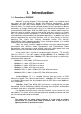
Power Indication LED Gi
g
abit Ethernet Port
RESET Button:
RESET button is used
to reset the
mana
g
ement s
y
stem.
Fiber Port Status Indication LEDs SFP Fiber Port
RS-232 DB-9 Connector
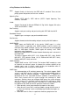
• LED Indic
ators
Fig. 1-2 Front View of SW24GF
LED Color Function
System LED
POWER
Green Lit when +5V DC power is on and good
10/100/1000Ethernet TP Port 1 to 8 LED
LINK/ACT
Green
Lit when connection with remote device is good
Blinks when any traffic is present
Off when cable connection is not good
10/100/1000Mbps
Green/
Amber
Lit green when 1000Mbps speed is active
Lit ember when 100Mbps speed is active
Off when 10Mbps speed is active
1000SX/LX Gigabit Fiber Port 1, 24 LED
SFP(LINK/ACT)
Green
Lit when connection with the remote device is good
Blinks when any traffic is present
Off when module connection is not good
Table1-1