Installation Guide KTI 10/100 Fast Ethernet Switch KS2028 P/N:750-0087-001 DOC.
Ó 1997 KTI Networks Inc. All rights reserved. No part of this documentation may be reproduced in any form or by any means or used to make any directive work (such as translation or transformation) without permission from KTI Networks Inc. KTI Networks Inc. reserves the right to revise this documentation and to make changes in content from time to time without obligation on the part of KTI Networks Inc. to provide notification of such revision or change.
10/100 Fast Ethernet Switch Installation Guide DOC.
The information contained in this document is subject to change without prior notice. Copyright Ó KTI. All Rights Reserved. TRADEMARKS Ethernet is a registered trademark of Xerox Corp. WARNING: This equipment has been tested and found to comply with the limits for a Class A digital device, pursuant to Part 15 of the FCC Rules. These limits are designed to provide reasonable protection against harmful interference when the equipment is operated in a commercial environment.
1. Table of Contents Introduction ............................................................................... 1 1.1 1.2 Features .................................................................................................................. 2 Specifications ......................................................................................................... 3 2. Installing the Switch .................................................................. 4 2.1 2.2 2.3 2.4 2.5 Packing List .....
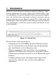
1. Introduction Driven by recent advances in desktop computing technology, today’s network applications have grown speed, power and the ability to process information. To meet the demands of these more powerful applications, the switch has been developed to alleviate congestion and improve performance on your Ethernet network. The switch comes with multiple ports, with each capable of transmitting or receiving information simultaneously at full wire speed to control and allocate the network bandwidth.
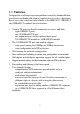
1.1 Features Designed for resolving congestion problems caused by bandwidth-hungry devices and bandwidth-intensive applications as well as a high number of users, the switch not only adheres to the IEEE 802.3 10BASE-T and 100BASE-T standard, but also features: • • • • • • • • Various TP ports for flexible connection to servers and hubs.
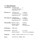
1.2 Specifications Network ports 10BASE-T ports 10/100BASE-TX port Expansion port slot 8 1 1 Filtering rate 10BASE-T ports 10/100BASE-TX port Expansion port slot 14,880 pps 148,800 pps 148,800 pps Forwarding rate 10BASE-T ports 10/100BASE-TX port Expansion port slot 14,880 pps 148,800 pps 148,800 pps Filtering address Multicast address Broadcast address Unicast address unlimited unlimited 8192 per port max.
2. Installing the Switch The switch is designed to operate in workgroup environments without a complicated configuration procedure. It also features an auto-select 100240V, 50/60Hz power supply unit, which works in most countries around the world. Before connecting the supplied power cord into the switch, check to see that the cord voltage and current rating conform to the standards of the country of operation. 2.
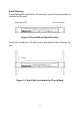
Rack Mounting For mounting the switch into a 19-inch rack, a pair of mount brackets is included in the pack.
2.3 Front Panel and Rear Panel Figure 2-4 Components on the Front and Rear Panel • • • • Eight 10BASE-T switched ports (Port #1 to Port #8) Each port consists of an RJ-45 connector and is used for connection to a 10BASE-T hub or node. One 10/100BASE-TX switched port (Port #9) The port consists of an RJ-45 connector and is used for connection to a 10BASE-T or 100BASE-TX device (hub or node).
• • Diagnostic LED indicators The indicators provide the operating status of the hub and the network ports. The status includes power, partition, duplex, activity, and collision. Configuration switches Two configuration switch groups are located on the rear of the switch unit. The switches are used for configuring the operation settings for all ports. The settings include mode, speed, and duplex. 2.
Figure 2-6 100BASE-FX Port Module Before installing any optional modules, first turn the power to the switch off. To install a module into the expansion port slot, follow these steps: 1. Turn off the power switch. 2. Remove the cover of the slot. Figure 2-7 Remove the Slot Cover 3. Align the connector and insert the module until it is fully seated. Secure it to front panel.
2.5 Setting the Configuration Switches Open the configuration switch cover on the rear of the unit. There are two switch groups as illustrated below: Figure 2-9 Configuration Switches The following table specifies the definition of each switch: The M switch only functions for Port #9 and Port #10. Since Port #1 to Port #8 are fixed 10BASE-T ports, the speed of these ports is fixed at 10Mbps. No speed selection is available.
When a operation mode is accepted by the remote device, the mode is used for the data transfer between the port and the connected device. Full-duplex operation enables two devices to transfer data bi-directionally at the same time.
3. Making Network Connections 3.1 Network Switched Ports There are ten ports on the switch for connection to ten LAN segments. Each segment is an independent shared network in one collision-domain. Figure 3-1 Network Ports Port #1 to Port #8 are 10Mbps-based 10BASE-T switched ports and dedicated for connecting to eight separate 10Mbps Ethernet segments through individual 10BASE-T connections. Port #9 is a 10/100Mbps-based dual-speed switched port.
3.2 10BASE-T Switched Ports The individual RJ-45 connectors of Port #1 to Port #7 are defined as X type connectors and have fixed pin assignments as follows: The following table lists the devices to which Port #1 to #7 can connect : Device connected Computer 10BASE-T port 10BASE-T hub port (I type) 10BASE-T switched port (I type) Cable used Cat. 3, 5 straight UTP Cat. 3, 5 straight UTP Cat.
The following table lists the devices to which Port #8 can connect : Device connected Crossover SW Computer 10BASE-T port X setting 10BASE-T hub port (I type) X setting 10BASE-T hub port (X type) I setting 10BASE-T switched port (I type) X setting 10BASE-T switched port (X type) I setting Cable used Cat. 3, 5 straight UTP Cat. 3, 5 straight UTP Cat. 3, 5 straight UTP Cat. 3, 5 straight UTP Cat. 3, 5 straight UTP Straight UTP Cable The cable is 2-pair Category 3 or 5 UTP and maximum length is 100 meters.
3.3 10/100BASE-TX Switched Ports This section applies to the 10/100BASE-TX Port #9 and expansion slot Port #10 pre-configured with a 10/100BASE-TX port module.
3.4 100BASE-FX Module The 100BASE-FX port module supports a connection to a Fast Ethernet network segment through a fiber optic connection. The module comes with two ST connectors. One labeled Tx is used for transmission. The other one labeled Rx is used for reception.
4. LED Indicators 4.1 LED Panel The switch provides comprehensive LED indicators for diagnosing and monitoring the operation of the unit as illustrated below: Figure 4-1 LED Indicators 4.2 Interpretation One Power LED indicates the status of the power supplied to the switch. Each port has two LEDs to indicate the port status including cable link, partition state, activity, collision, and duplex mode. Every port has identical interpretations for the LED display. The LED can display two different colors.