KGS-2402 Web Samrt 24-Port Gigabit Ethernet Switch with SFP support Installation Guide DOC.
(C) 2005 KTI Networks Inc. All rights reserved. No part of this documentation may be reproduced in any form or by any means or used to make any directive work (such as translation or transformation) without permission from KTI Networks Inc. KTI Networks Inc. reserves the right to revise this documentation and to make changes in content from time to time without obligation on the part of KTI Networks Inc. to provide notification of such revision or change.
The information contained in this document is subject to change without prior notice. Copyright (C). All Rights Reserved. TRADEMARKS Ethernet is a registered trademark of Xerox Corp. WARNING: This equipment has been tested and found to comply with the limits for a Class A digital device, pursuant to Part 15 of the FCC Rules. These limits are designed to provide reasonable protection against harmful interference when the equipment is operated in a commercial environment.
Table of Contents 1. Introduction ................................................................................................... 6 1.1 Features .................................................................................................................... 6 1.2 View of Web Smart 24-Port Gigabit Switch ............................................................... 7 1.3 Hardware Specifications ........................................................................................... 8 1.
3.3 Monitoring ................................................................................................................ 32 3.3.1 Statistics Overview ............................................................................................... 32 3.3.2 Detailed Statistics ................................................................................................. 33 3.4 Maintenance ............................................................................................................
1. Introduction Before you start installing the switch, verify that the package contains the following: • Web Smart 24-Port 10/100/1000 Gigabit Ethernet Switch unit • 19" rack mounting brackets • This User Manual in CD-ROM • AC Power Cord 1.1 Features • • • • • • • • • • • Non-blocking store-and-forward Web-Smart switched.
1.
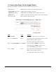
1.3 Hardware Specifications Standard Compliance: IEEE802.3/802.3ab / 802.3z / 802.3u / 802.3x Network Interface: Configuration Mode Connector Port 10/100/1000Mbps Gigabit Copper NWay RJ-45 1 - 24 1000Base-X Gigabit Fiber 1000 FDX SFP* 23,24(Option) *Port 23, 24 are RJ-45/SFP fiber dual media ports with auto detected function. *Optional SFP modules support MMF, SMF LC or BiDi LC transceiver.
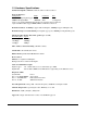
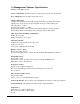
1.4 Management Software Specifications Interface : Web Http browsing System configuration: IP address settings, system name, password, Auto-logout timer Port configuration: Port operating mode, flow control VLAN configuration VLAN mode : disable, Port-based, 802.
2. Installation 2.1 Safety Cautions To reduce the risk of bodily injury, electrical shock, fire, and damage to the equipment, observe the following precautions. • Do not service any product except as explained in your system documentation. • Opening or removing covers may expose you to electrical shock. • Only a trained service technician should service components inside these compartments.
2.5 Port and Cable Connection 10/100M copper connection 1000M copper connection 1000M fiber connection Cables Cat.3, 4, 5, Cat.5 is recommended Cat. 5, 5e, Cat. 5e is recommended MMF or SMF depending on the SFP transceiver used 2.6 Rack Mounting Two 19-inch rack mounting brackets are supplied with the switch for 19-inch rack mounting. The steps to mount the switch onto a 19-inch rack are: 1. Turn the power to the switch off. 2. Install two brackets with supplied screws onto the switch. 2.
3. Operation of Web-based Management The steps to start web management are: 1. Type http://192.168.1.1 in the address row in a browser. 2. Type password in order to login and access authentication. The default password is [admin]. Login For the first time to use, please enter the default password, then click the button. The login process now is completed. In the switch, it supports a simple user management function allowing only one administrator to configure the system at the same time.
3.1 Web Management Home Overview The Information of Page Layout Top side It shows the front panel of the switch. In the front panel, the linked ports will display green; as to the ports, which are link off, they will be dark. For the optional modules, the slot will show only a cover plate if no module exists and will show a module if a module is present. The image of module depends on the one you inserted. The same, if disconnected, the port will show just dark, if linked, green.
3.2 Configuration Each of them will be described in detail orderly in the following sections.
3.2.1 System Configuration The switch supports manual IP address setting. When IP address is changed, you must reboot the switch to have the setting taken effect and use the new IP to browse for web management. Parameter description: MAC Address It is the Ethernet MAC address of the management agent in this switch. Firmware Version The firmware version of this switch. Hardware Version The hardware version of this switch. Serial Number The serial number is assigned by the manufacturer.
3.2.2 Ports Configuration Parameter description: Mode Set the speed and duplex of the port. Speed/Duplex is comprised of the combination of speed mode, 10/100/1000Mbps, and duplex mode, full duplex and half duplex. In Auto Speed mode, no default value. In Forced mode, default value depends on your setting. Flow Control There are two modes to choose in flow control, including Enable and Disable.
3.2.3 VLAN Mode Configuration The switch supports Port-based VLAN and 802.1Q Tag-based VLAN. Support 24 active VLANs and VLAN ID 1~4094. Parameter description: VLAN Mode Disable - Stop VLAN function on the switch. In this mode, no VLAN is applied to the switch. This is the default setting. Port-based - Port-based VLAN is defined by port. No filtering criterion applies in port-based VLAN. The only criterion is the physical port you connect to. Tag-based - Tag-based VLAN identifies its member by VID.
3.2.4 VLAN Group Configuration It shows the existed information of VLAN Groups List and maintains them, i.e. modify and delete one of them. You can easily create and delete a VLAN group by pressing and function buttons, or click the Group ID directly to edit it. Parameter description: ID (Group ID) When you want to edit a VLAN group, you must select the Group ID field.
Add a Tag-based VLAN group Just tick the check box (t) beside the ID, then press the button to delete the group.
3.2.5 PVID Configuration This configuration is applied to Tag-based VLAN mode only. Parameter description: Port 1-24 Port number. PVID This PVID range will be 1-4094. Before you set a number x as PVID, you have to create a Tag-based VLAN group with VID x. Rule 1 Forward only packets with VID matching this port configured VID. You can apply Rule 1 as a way to a given port to filter unwanted traffic. Rule 2 Drop untagged frame.
3.2.6 Aggregation Configuration The Aggregation (Port Trunking) Configuration is used to configure the settings of Link Aggregation. You can bundle more than one port with the same speed, full duplex and the same MAC to be a single logical port, thus the logical port aggregates the bandwidth of these ports. Parameter description: Normal Set up the ports that do not join any aggregation trunking group. Group 1~8 Group the ports you choose together. Up to 12 ports can be selected for each group.
3.2.7 Mirror Configuration Mirror Configuration is to monitor the traffic of the network. For example, we assume that Port A and Port B are Sniffer Port and Source Port respectively, thus, the traffic passed by Port B will be copied to Port A for monitoring. Parameter description: Sniffer Mode Used for the activation or deactivation of Port Mirror function, the switch port mirror supported Ingress traffic only. Default is disable. Sniffer Port Set up the port for monitoring.
3.2.8 Quality of Service Configuration Function description: Default Class Some packets which did not belong to the selected QoS classification method would be classified as Default Class. [VLAN Tag Priority] In VLAN-tagged packet, there are 3 bits belonging to priority. According to these 3 bits, we could arrange 8 traffics -0 0 0, 0 0 1, 0 1 0, 0 1 0, 1 0 0, 1 0 1, 1 1 0, 1 1 1. We can set High priority or Low priority for each traffic class.
3.2.8.1 Vlan Tag Configuration Parameter description: Port Port 1 ~ Port 24 - User can set up the port (1~24) respectively to let Vlan Tag QoS function work on them. Multiple port selection is allowed. All - select all ports (1~24) to simplify the procedure of configuration. Class Each priority tag value is configured with a priority class. High - High Priority Low - Low priority Note: 1. Bit 0 Bit 1 Bit 2 represent the 3-bit value in priority tag field. 2.
3.2.8.2 IP ToS Classification Parameter description: Port Port 1 ~ Port 24 - User can set up the port (1~24) respectively to let IP ToS QoS Classification function work on them. Multiple port selection is allowed. All - select all ports (1~24) to simplify the procedure of configuration. Class Each ToS value is configured with a priority class. High - High Priority Low - Low priority Note: Bit 0, Bit 1, Bit 2 represent Bit 5 ~ Bit 7 in TOS Field of IP Header in an IP packet.
3.2.8.3 IP TCP/UDP Port Classification In L4 QoS Configuration, you can select one of these special network transmission events with the associated predefined configuration. Or, click to view the detailed configuration and make change for customizing.
Advanced Mode: Special TCP/UDP class: Class assigned to the configured Custom Port numbers High - High Priority Low - Low priority Default class (all other TCP/UDP ports): The class assigned to the port numbers that are not in the Custom port list. Port Port 1 ~ Port 24 - User can set up the port (1~24) respectively to let L4 QoS Classification function work on them. Multiple port selection is allowed. All - select all ports (1~24) to simplify the procedure of configuration.
3.2.8.4 IP Diffserv Classification IP Diffserve Classification method uses 6-bit field of DSCP in an IP packet to classify the priority class of the received IP packet. Each DSCP (Diffserv value) can be configured a priority class. Parameter description: Diffserv: Display 64 (0~63) DSCP items. Class: Class assigned to the DSCP High - High Priority Low - Low priority Note: The classification function are applied to all ports and can not be configured for each port respectively..
3.2.9 Bandwidth Management Bandwidth Management function is used to set up the limit of Ingress and Egress bandwidth for each port. Note: Each port of the switch owns 16KB packet buffer. The packet buffer size will be reduced when the bandwidth rate limitation is enabled, which may cause that jumbo frame cannot be forwarded. Avoid enabling jumbo frame and bandwidth rating functions at the same time.
3.2.10 Trap Event Configuration The Trap Events Configuration function is used to enable the switch to send out the SNMP trap information while predefined trap events occurred. Parameter description: Trap IP: IP address of the SNMP trap manager who can receive the traps. Two trap managers are supported.
3.2.11 Max. Packet Length This function is used to limit the maximum packet length accepted by each port. Jumbo Frame(bytes) Set up the maximum length of the packet that each port can accept. Options : 1518, 1532, 9216 bytes The default is 1532 bytes.
3.3 Monitoring There are two functions contained in the monitoring section. 3.3.1 Statistics Overview The function of Statistics Overview collects any information and provides the counting summary about the traffic of the port, no matter the packet is good or bad. If the counting is overflow, the counter will be reset and restart counting. Parameters description: Tx Bytes Total transmitted bytes. Tx Frames The counting number of the packet transmitted. Rx Bytes Total received bytes.
3.3.2 Detailed Statistics Parameter description: Rx Packets The counting number of the packet received. RX Octets Total received bytes. Rx High Priority Packets Number of Rx packets classified as high priority. Rx Low Priority Packets Number of Rx packets classified as low priority. Rx Broadcast Show the counting number of the received broadcast packet. Rx Multicast Show the counting number of the received multicast packet. Tx Packets The counting number of the packet transmitted.
Rx 65-127 Bytes Number of 65 ~ 126-byte frames in all packets received. Rx 128-255 Bytes Number of 127 ~ 255-byte frames in all packets received. Rx 256-511 Bytes Number of 256 ~ 511-byte frames in all packets received. Rx 512-1023 Bytes Number of 512 ~ 1023-byte frames in all packets received. Rx 1024-Bytes Number of 1024-max_length-byte frames in all packets received. Tx 64 Bytes Number of 64-byte frames in all packets transmitted.
3.4 Maintenance The functions are supported: Status Display all configuration and status of the switch Warm Start Perform a reboot for the switch Factory Default Restore all settings back to factory default values Software Update Perform an update to the management firmware of the switch Logout Perform a logout from the switch 3.4.
Each of them will be described in detail orderly in the following sections. System Status Product Name: To show the product name of this device. Firmware Version: To show the firmware version of this switch. Hardware Version: To show the hardware version of this switch. Serial Number: The serial number is assigned by the manufacturer. IP Address: To show the IP address of this switch. Subnet Mask: To show the subnet mask of this switch.
Mirror Sniffer Mode: Display the status the activation or deactivation of Port Mirror function. Sniffer Port: Display the port for monitoring. Source Port: Display the port for being monitored.
3.4.3 Factory Default Factory Default function can restore settings back to factory default values except the IP address settings.
3.4.4 Software Update The switch supports the software update function for the user to upgrade the firmware of the switch to the latest software version. Click this function and press the button, then you will enter next two pages to complete the software updating procedures. You must complete the updating procedure.
3.4.5 Logout Besides the Auto Logout Timer function described in the section of System Configuration, the switch also allows the user to logout manually by performing the Logout function. If no action and no key is stroke as well in any function screen more than the minutes you set up in Auto Logout Timer, the switch will have you logout automatically. Or press the button in Logout function to exit the system manually.