Installation Guide Web Smart Managed 10/100 Fast Ethernet Switches with VLAN Support KS-115FM-V KS-117FM-V DOC.
(C) 2002 KTI Networks Inc. All rights reserved. No part of this documentation may be reproduced in any form or by any means or used to make any directive work (such as translation or transformation) without permission from KTI Networks Inc. KTI Networks Inc. reserves the right to revise this documentation and to make changes in content from time to time without obligation on the part of KTI Networks Inc. to provide notification of such revision or change.
The information contained in this document is subject to change without prior notice. Copyright (C) All Rights Reserved. TRADEMARKS Ethernet is a registered trademark of Xerox Corp. This device complies with Class A Part 15 the FCC Rules. Operation is subject to the following two conditions: (1) This device may not cause harmful interference, and (2) this device must accept any interference received including the interference that may cause.
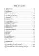
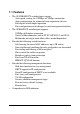
Table of Contents 1. Introduction .................................................................. 5 1.1 Features ........................................................................................... 6 1.2 Specifications .................................................................................. 7 1.3 FX Port Optical Specifications ......................................................... 8 1.4 Management Specifications ............................................................ 9 2.
1.
1.
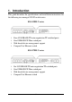
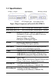
1.2 Specifications Figure : Major Components on Panels (Ex. KS-117FM-V) KS-115FM P1-P4 Port 1 ~ Port 4 Twisted-pair switched ports (TP ports) KS-117FM P1-P6 Port 1 ~ Port 6 Twisted-pair switched ports (TP ports) TP Port IEEE 802.3 10BASE-T, IEEE 802.3u 100BASE-TX std. Shielded RJ-45 jacks with Auto MDI-X detection Auto-negotiation capable Speed for 10Mbps or 100Mbps Full-duplex or half-duplex support FX Port IEEE 802.3u 100BASE-FX compliant Fixed 100Mbps Full-duplex operation Flow control IEEE 802.
Filtering address Multicast/Broadcast/Unicast address MAC address 2K entries Aging time 300 seconds Priority levels 2 outgoing priority queues (Ratio: High/Low = 4/1 ) VLAN mode VLAN groups Port PVID Port Tag Mode 1. Port-based VLAN 2. 802.1Q VLAN (Tag-based) 16 groups (Group 0 ~ 15) Full 12-bit VID, per port setting Tag/Untag mode, per port setting Environment Temperature 0oC to 40oC Relative humidity 10% to 90% non-condensing Dimensions 144 mm x 100 mm x 26 mm (WxDxH) 5.67 x 3.94 x 1.
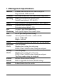
1.4 Management Specifications Interface In-band web browser for IE4.0 and Netscape4.x Ping command, ARP command Protocols IPv4, ARP, ICMP, UDP, TCP, DHCP client, Http server IP Setting DHCP dynamic IP mode (default mode) Static IP mode (default : 192.168.0.
2. Installing the Switches 2.1 Unpacking Check to see that you have everything before you start the installation. • Installation guide • The switch unit • Rubber magnet stand • One AC power adapter for the unit 2.2 Supply the Power Checking AC Power Before you begin the installation, check the AC voltage of your area. The AC power adapter which is used to supply the DC power for the unit should have the AC voltage matching the commercial power voltage in your area.
2. Connect the power adapter cable to the switch before connecting the adapter to the AC outlet. 2.3 Port Configuration The switches provide port configuration function through the management interface.
2.4 VLAN Function The switches support two VLAN modes. One is Port-based VLAN and the other is 802.1Q VLAN. The following configuration are supported: 1. VLAN Mode : Port-based mode or 802.1Q mode 2. VLAN mapping table setup : member ports setup for each group 3. Per port PVID setup : PVID setting, Tag mode setting Port-based VLAN Mode 1. This mode supports 16 VLAN groups, Group 0 ~ Group 15. 2. Packet forwarding is performed only among the member ports in same group. 3.
802.1Q VLAN Mode 1. This mode supports 16 VLAN groups, Group 0 ~ Group 15. 2. When an untagged packet is received, the associated PVID setting of the input port is used to map to one VLAN group in VLAN group table. The mapping index is retrieved from the least 4 bits (bit 3~0) of the PVID value. 3. When a tagged packet is received, the VLAN ID value of the received packet is used to map to one VLAN group in VLAN group table.
Summary of VLAN Group Lookup (Group Mapping Index) Input Packet Type Untagged packet Tagged packet Port-based VLAN Mode 802.
2.5 DHCP and IP Configuration Each switch must be designated an IP address before it can be managed from web browser. Basically, the switches provide two methods for IP configuration: 1. DHCP mode The switch requests a dynamic IP address from the first discovered DHCP server in the network when boot up. In general, the assigned IP can be monitored in the client list on the DHCP server. The model name and MAC address of the switch is referred as the DHCP client ID.
2.7 Making UTP Connections TP Port Configuration Use management function to set the required TP port configuration. It is recommended to set the highest ability for the TP ports as follows: Auto-negotiation = enabled Speed = 100M Duplex = Full This is appropriate to support connection to almost every Ethernet devices including those which are not auto-negotiation capable.
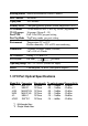
2.8 Making Fiber Connection For different fiber connections, several alternative models can be selected for different fiber connections as follows: Model Ext. -T -C -JM -VM -L -SA2 Connector ST SC MT-RJ VF-45 LC SC Cable Max. Distance* MM 2 Km MM 2 Km MM 2 Km MM 2 Km MM 2 Km SM 20 Km *: The maximum distance connecting to a full duplex device The recommended multimode fiber is 62.5/125mm and 9/125mm for single mode fiber.
2.9 LED Indications Functions POWER : 100/10 : LINK/Act. : FDX/Col. : indicates the status of the power supplied to the switch. indicates the connection speed between the TP port and the associated connected device. indicates the port link and activity status indicates the duplex mode and collision occurrences The following table lists the LED states and the indications: LED POWER POWER 100/10 100/10 LINK/Act. LINK/Act. LINK/Act.
3. Web Management 3.1 Web Browser The system features an http server which can serve the management requests coming from any web browser software over internet or intranet network. Web Browser Compatible web browser software with JAVA support Microsoft Internet Explorer 4.0 or later Netscape Communicator 4.x or later Start connection Before the switch can be managed from a web browser software, the switch IP address is required. Consult your LAN administrator if it is not available.
Enter your password and click [OK] to login into the switch. The switch comes with factory default password : 123.
The web page is shown as follows when a successful login is performed: The left side shows the switch model and menu list.
3.2 Port Setup The middle part of previous figure shows all port status of the connected switch. The right side shows port configuration setup page. Port Status Port Status page displays the current port status.
3.3 IP Setup This page includes the following functions: IP Status Display information of current IP used If the current IP address is labeled (DHCP), it means the IP is assigned by DHCP server. IP Setup Set static IP address to be used when DHCP is disabled or when no DHCP server is available. DHCP Setup Enable to get and use dynamic IP address assigned by DHCP server. Disable to use Static IP setting. Any change or click [Apply] do not affect current management connection.
3.4 VLAN Setup VLAN Mode Select Port-based VLAN : Port-based VLAN 802.1Q base VLAN : IEEE 802.1Q Tag-based VLAN Click [Apply] to make change effective immediately. Note: 1. Both modes use same group member port settings and Port PVID settings. When selecting Port-based VLAN, all ports are set to Untag ports automatically. 2. Under Port-based VLAN mode, all packets are forwarded transparently with no packet modification.
3.4.1 Port-based VLAN Click [VLAN Mapping Table] This page is used to setup member ports for each VLAN group. Total of 16 VLAN groups are supported. The steps to configure the member ports are: 1. Select Group number : 0 ~ 15. 2. Set [Yes] on the selected port to include it into the member port list. Note: One port can belong to more than one VLAN groups. VLAN group table mapping index is based on the least four bits (bit 3 ~ bit 0) of the PVID of the input port.
Click [Port PVID Setting] This page is used to setup PVID and Tag mode for each port as follows: PVID : The setting value is used for VLAN group lookup index. When a packet is received, the least four bits (bit 3~bit 0) of the PVID setting of the input port is used as the index mapping to one VLAN group. The mapped group is used for packet forwarding operation. The valid value range is 1 ~ 4095. Refer to section 2.4 for more information about the MNG port.
3.4.2 802.1Q VLAN Click [VLAN Mapping Table] This page is used to setup member ports for each VLAN group. Total of 16 VLAN groups are supported. Actually, the table are shared by Portbased VLAN mode and 802.1Q VLAN mode. The steps to configure the member ports are: 1. Select Group number : 0 ~ 15. 2. Set [Yes] on the selected port to include it into the member port list. 802.
Click [Port PVID Setting] This page is used to setup PVID and Tag mode for each port as follows: PVID : The valid value range is 1 ~ 4095. The setting value is used for the following purposes: 1. It is used as VLAN group lookup index when an untagged packet is received. The least four bits (bit 3~bit 0) of the PVID setting of the input port is used for mapping to one VLAN group. 2. It is used to be inserted into the packet as VID when an untagged packet is received and forwarded to a Tag port.
Tag Mode : Setting for each port to be Tag port or Untag port for outbound. Tag port - All output packets are tagged. Untag port - All output packets are untagged. Depending on the received packet type, the rules are applied as follows: Received untagged packet output to: Tag port : The packet is inserted with PVID of the input port as VLAN ID and new CRC. Untag port : The packet is forwarded with no change. Received tagged packet output to: Tag port : The packet is forwarded with no change.
.5 Password Setup Password is used for checking authority for accessing the switch. To change password setting, enter your new password and reconfirm the input again. Click [Apply] to apply the new password immediately.
3.6 Restore Default This command is used to restore all settings back to factory default values. Click [Restore] to apply immediately. Refer to Appendix for factory default values.
3.7 ReBoot Device The command is used to reboot the switch remotely over the network. Normally, it is used after IP settings are changed.
3.8 About About page shows switch model name and software version.
Appendix: Factory Default Values Settings DHCP mode Static IP address Netmask Default gateway IP Login password TP ports TP port speed TP port duplex VLAN mode VLAN group table Port PVID Tag mode Factory Default Values Enabled 192.168.0.2 255.255.255.0 192.168.0.1 123 Auto-negotiation enabled 100M (the highest ability) Full duplex (the highest ability) Port-based VLAN enabled 802.