BEDIENUNGSANLEITUNG2004 125 200 250 300 SX, EXC SX, EXC SX, EXC MXC, EXC OWNER`S MANUAL MANUALE D`USO MANUEL D`UTILISATION MANUAL DE INSTRUCCIONES ART.NR: 3.210.
IMPORTANT PLEASE READ THIS MANUAL CAREFULLY AND COMPLETELY BEFORE GOING ON YOUR FIRST RIDE. IT CONTAINS A GREAT DEAL OF INFORMATION AND ADVICE WHICH WILL HELP YOU USE AND HANDLE YOUR BIKE PROPERLY. IN YOUR OWN INTEREST, PLEASE PAY PARTICULAR ATTENTION TO NOTICES THAT WARNING IGNORING THESE INSTRUCTIONS, CAN BE DANGEROUS TO LIFE AND LIMB. ! CAUTION ! IGNORING THESE INSTRUCTIONS MAY DAMAGE PARTS OF THE MOTORCYCLE OR IMPAIR THE MOTORCYCLE’S TRAFFIC SAFETY.
Introduction We would like to congratulate you on your purchase of a KTM motorcycle. ENGLISH 2 You are now the owner of a state-of-the-art sports motorcycle that guarantees to bring you lots of fun and enjoyment, provided that you clean and maintain it appropriately.
IMPORTANT WARRANTY AND GUARANTEE INFORMATION Observance of the service, maintenance and tuning instructions for the engine and chassis specified in the Owner's Manual is a prerequisite for faultless operation and the avoidance of premature wear. An improperly tuned chassis can lead to damage and breakage of the chassis components (see chapter on checking the basic chassis setting).
TABLE OF CONTENTS Page IMPORTANT WARRANTY AND GUARANTEE INFORMATION .3 SERIAL NUMBER LOCATIONS . . . . . . . . . . . . . . . . . . . . . . .5 Chassis number . . . . . . . . . . . . . . . . . . . . . . . . . . . . . . . .5 Engine number, engine type . . . . . . . . . . . . . . . . . . . . . .5 ENGLISH 4 OPERATION INSTRUMENTS . . . . . . . . . . . . . . . . . . . . . . . .5 Clutch lever . . . . . . . . . . . . . . . . . . . . . . . . . . . . . . . . . .5 Hand brake lever . . . . . . . . . . . . . . . . . .
SERIAL NUMBER LOCATIONS Chassis number Engine number, engine type The engine number and the engine type are stamped into the left side of the engine below the engine sprocket. Enter this number on page 1. ENGLISH The chassis number is stamped on the right side of the steering head tube. Enter this number in the field on page no 1. 5 OPERATION INSTRUMENTS Clutch lever 1 The clutch lever 1 is located on the left side of the handlebars.
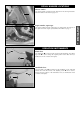
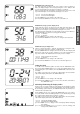
Electronic speedometer, indicator lamp (EXC) 1 The green control lamp 1 flashes in the same rhythm as the flashing indicator when the indicator is working. The blue control lamp 2 lights up when the high beam is on. 2 ENGLISH Electronic speedometer The electronic speedometer display is activated as soon as the engine is switched on and the motorcycle starts to move. The engine must be started in order for the speedometer to be supplied with electricity from the generator.
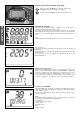
– The switch has three buttons: MODE, + (plus) and – (minus). MODE WARNING DO NOT TRY TO CHANGE THE MODE OR READ THE SETTINGS WHILE DRIVING. YOUR ATTENTION WILL BE DISTRACTED FROM THE TRAFFIC WHICH CAN EASILY LEAD TO AN ACCIDENT. Electronic speedometer functions provided by the Tripmaster switch The display modes on the electronic speedometer will change in the following order. If not, please read the chapter "ACTIVATING AND DEACTIVATING THE DISPLAY MODE.
SPEED/CLK (clock) display mode CLK will display time in hours, minutes and seconds. + BUTTON no function – BUTTON no function press the MODE BUTTON to change to the next mode. press and hold the MODE BUTTON 3 SECONDS to set the time in the menu (see SETTING THE CLOCK) ENGLISH 8 SPEED/H (hours) display mode When you stop driving and no impulses are sent from the wheel sensor, the display mode will automatically change from SPEED/ODO to SPEED/H. H shows the operating hours.
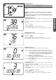
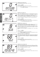
SPEED/TRP2 (trip 2) display mode The TRP2 trip meter is always active and counts to 999.9. Contrary to TRP1, the displayed figure can be changed using the + and – buttons. This is a very useful function for trips taken according to a roadbook. TRP2 is activated by the first impulse received from the wheel sensor and stops automatically 3 seconds after the last impulse is received. SPEED/AVS2 (average speed 2) display mode AVS2 shows the average speed based on the TRP2 and STP2 figures.
Kilometers or miles The unit (kilometers or miles) can also be changed. The ODO figure will be retained and converted accordingly. The TRP1, AVS1, STP1, TRP2 and AVS2 figures will be cleared. To select the unit, select the SPEED/H mode and hold the MODE button for 3 seconds to access the SETUP menu. Press the MODE button 10 times until the KMH/MPH function blinks. Press the + button to move to the options. Press the + button for KMH or the – button for MPH.
Short circuit button (SX) The short circuit button 1 turns off the engine. When pressing this button, the ignition circuit is short-circuited. Combination switch (EXC) 3 2 The light switch has 2, respectively 3 switch positions. A = Light off (this function is not available in all models) B = Low beam on C = High beam on You may use button 2 to actuate the horn. The red short circuit button 3 serves to switch off the engine. Leave the switch pressed until the engine stops.
Filler cap To open it: turn filler cap counter-clockwise. To close it: put filler cap back on and tighten it by turning it clockwise. Install tank breather hose 1 without kinks. 1 ENGLISH Fuel tap OFF In this position the fuel tap is closed. No fuel can flow to the carburetor. ON During operation the twist grip must be turned to ON. This means that the fuel can flow to the carburetor. With the twist grip in this position the tank will be emptied until only the reserve is left.
Kickstarter Foot brake pedal The foot brake pedal is disposed in front of the right foot rest. Its basic position can be adjusted to your seat position (see maintenance work). ENGLISH The kickstarter is mounted on the left side of the engine. Its upper part can be swivelled. 13 Side stand 1 Push the side stand to the ground with your foot and load it with the motorcycle. Make sure that you put your bike on solid ground and in a secure position.
Compression damping of fork 1 2 2 Hydraulic compression damping determines the reaction when the fork is compressed. The degree of compression can be adjusted with adjusting screws at the bottom of the fork legs.Remove the protecting cap 1. Turn the knob 2 clockwise to increase damping, turn it counterclockwise to reduce damping during compression.
Compression damping of shock absorber (MXC, EXC) The compression damping (during compression) can be adjusted for the MXC and EXC shock absorbers (Mono Compression Control). The degree of damping can be adjusted by turning adjusting screw 1 with a screwdriver. Turning in a clockwise direction will increase the damping, turning in a counterclockwise direction will decrease the damping. 2 STANDARD ADJUSTMENT: – Turn the adjusting screw clockwise to the stop.
GENERAL TIPS AND WARNINGS FOR STARTING THE MOTORCYCLE Instructions for your first ride ENGLISH 16 – Verify that your KTM dealer performed the PREPARATION OF VEHICLE jobs (see Customer Service Manual). – Thoroughly read the whole instruction manual before starting for your first tour. – Familiarize yourself with the controls. – Adjust the clutch lever, the hand brake lever and the foot brake pedal to the most comfortable position.
DRIVING INSTRUCTIONS What you should check before each start When you start off, the motorcycle must be in a perfect technical condition. For safety reasons, you should make it a habit to perform an overall check of your motorcycle before each start. The following checks should be performed: 2 FUEL Check that there is sufficient fuel in the tank; when closing the filler cap, check that the tank venting hose is free of kinks.
Starting when the engine is cold 1 2 3 4 5 ENGLISH 18 Open fuel tap Turn on ignition or emergency OFF switch Put the gear in neutral Activate cold-starting aid (choke) Leave throttle closed or open it no more than 1/3 and kick down kickstarter vigorously all the way. WARNING – FOR STARTING ALWAYS PUT ON YOUR MOTORCYCLE BOOTS TO AVOID INJURIES. YOU COULD SLIP OFF THE KICKSTARTER OR THE MOTOR COULD KICK BACK AND FLING YOUR FOOT UPWARDS.
CAUTION ! – HIGH RPM RATES WHEN THE ENGINE IS COLD HAVE AN ADVERSE EFFECT ON THE LIFE OF YOUR ENGINE. WE RECOMMEND YOU RUN THE ENGINE IN A MODERATE RPM RANGE FOR A FEW MILES GIVING IT A CHANCE TO WARM UP. AFTER THAT NO FURTHER PRECAUTIONS IN THIS RESPECT NEED TO BE TAKEN. – NEVER HAVE THE THROTTLE WIDE OPEN WHEN CHANGING DOWN TO A LOWER GEAR. THE ENGINE WILL OVERREV, DAMAGING THE VALVES. IN ADDITION, THE REAR WHEEL WILL BLOCK SO THAT THE MOTORCYCLE CAN EASILY GET OUT OF CONTROL.
125/200 SX/EXC 250/300 SX/MXC/EXC PERIODIC MAINTENANCE SCHEDULE BRAKES CHASSIS WHEELS ENGLISH 20 ADD-ON-PARTS CARBURETOR ENGINE A clean motorcycle can be checked more quickly which saves money! Check gear box oil level Change gear box oil Check spark plugs, adjust distance between electrodes Renew spark plugs Check the carburetor connection boot for cracks and leaks Check idle speed setting Check that vent hoses are not damaged or bent Check cooling system for leaks, check quantity of antifreeze Chec
CARRIED OUT BY THE ● ● ● ● ● ● ● ● ● ● ● ENGLISH Check gear box oil level Check brake fluid level Check brake pads for wear Check lights for function Check horn for function Lubricate and adjust cables and nipples Bleed fork legs regulary Remove and clean dust bellows regularly Clean and lubricate chain, check tension and adjust if necessary Clean air filter and filter box Check tires for pressure and wear Check cooling liquid level Check fuel lines for leaks Empty and clean float chamber Check all co
RECOMMENDED INSPECTION OF THE 125/200/250/300 SX AND EXC ENGINE USED FOR ENDURO COMPETITIONS BY YOUR KTM WORKSHOP (ADDITIONAL ORDER FOR THE KTM WORKSHOP) ENGLISH Check the reed-type intake valve for wear Check the clutch shoes for wear Check the length of the clutch springs Check the cylinder and piston for wear Check the exhaust control for proper functioning and smooth running Check the eccentricity of the crankshaft journal Check the radial clearance of the conrod bearings Check the radial clearance of
23 ENGLISH
MAINTENANCE WORK ON CHASSIS AND ENGINE WARNING MAINTENANCE AND ADJUSTING WORK MARKED WITH AN ASTERISK (*) REQUIRES EXPERT SKILLS AND TECHNICAL KNOW-HOW. FOR YOUR OWN SAFETY, ALWAYS HAVE SUCH WORK PERFORMED BY A SPECIALIZED KTM DEALER WHERE YOUR MOTORCYCLE WILL BE OPTIMALLY SERVICED BY APPROPRIATELY QUALIFIED, SKILLED STAFF.
How to change the handlebar position 3 4 mm 15 2 3,5 mm For this purpose, remove screws 3 of the handlebar clamps and screws 4 of the handlebar support. Position the handlebar support, and tighten screws 4 to 40 Nm (30 ft.lbs). Mount the handlebar and handlebar clamps, and tighten screws 3 to 20 Nm (15 ft.lbs). The gap between the handlebar support and the handlebar clamps should be the same size in the front and in the rear. WARNING THE SCREWS 4 MUST BE SECURED WITH LOCTITE 243.
Basic suspension setup for the weight of the driver A To achieve maximum handling performance and to prevent the fork, shock absorber, swing arm and frame from being damaged, the basic setup of the suspension components must be suitable for your weight. At delivery, KTM's offroad motorcycles are set to accommodate a driver weighing 70 80 kg (wearing full protective clothing).
MODELL 1218Y767 125/200 SX SOFTER STANDARD HARDER 76/250 80/250 84/250 80/250 84/250 88/250 84/250 88/250 92/250 According to our experience, the damping rate of the compression stage can remain unchanged. The damping rate of the rebound stage can be reduced by a few clicks for a softer spring or increased by a few clicks for a harder spring. 1218Y768 125/200 EXC 1218Y769 250 SX 1218Y770 250/300 MXC, EXC The precise riding sag of the telescopic fork cannot be determined for various reasons.
Adjusting the spring preload on the fork (SX) The spring preload on the SX models can be adjusted (changed) by 10 mm by turning adjusting screw 1. Turning in a clockwise direction will increase the prestress, turning in a counterclockwise direction will decrease the prestress. Changing the spring preload will not affect the rebound damping adjustment. Generally, if the spring preload is higher, the rebound damping should also be set higher.
Check chain tension Jack the motorcycle up on its frame so that the rear wheel no longer touches the ground. Press the chain upward at the end of the chain sliding component. The distance between the chain and the swing arm should be approx. 8 - 10 mm (0.31 - 0.39 in). In the course of this procedure, the upper chain portion A must be taut (see drawing). If necessary, correct the chain tension.
Chain maintenance For long chain life, good maintenance is very important. X-ring chains require only modest maintenance. The best way is to use lots of water, but never use brushes or solvents. After letting the chain dry, you can use a special X-ring chain spray (Motorex Chainlube 622). WARNING NO LUBRICATION IS ALLOWED TO REACH THE REAR TIRE OR THE BRAKE DISK, EITHERWISE THE ROAD ADHERENCE AND THE REAR WHEEL BRAKING EFFECTS WOULD BE STRONGLY REDUCED AND THE MOTORCYCLE COULD EASILY GET OUT OF CONTROL.
General information about KTM disc brakes BRAKE CALIPERS: The brake calipers of this series use a ”floating” mount. This means that the brake calipers are not solidly attached to the caliper support, which enables them to ”float” for maximum braking contact.Secure the screws of the caliper support with Loctite 243 and tighten to 25 Nm (19 ft.lb). A B 1 Other brake pads are available for competition sports.
Adjusting the free travel at the hand brake lever min. 3 mm 1 Free travel at the hand brake lever may be readjusted by using adjustment screw 1. In this way, the position of the point of pressure (i.e. the resistance you feel on the hand brake lever when the brake pads are pressed against the brake disc) can be adjusted for any hand size. When you press the hand brake lever forwards, you should have at least 3 mm free travel. Turn the adjusting screw 1 if necessary.
Replacing the front brake pads * 1 2 1 3 WARNING – IT IS VERY IMPORTANT TO KEEP THE BRAKE DISK FREE FROM OIL AND FATTY MATTERS. OTHERWISE, THE BRAKING EFFECT WOULD BE STRONGLY REDUCED. – AFTER ASSEMBLY, CHECK IF CIRCLIPS HAVE BEEN FITTED CORRECTLY. – AFTER WORKING ON THE BRAKING SYSTEM, ALWAYS ACTUATE THE HAND BRAKE LEVER OR FOOT BRAKE LEVER, RESPECTIVELY TO ENSURE THAT THE BRAKE PADS WILL LIE AGAINST THE BRAKE DISK AND THE PRESSURE POINT IS ESTABLISHED.
Checking the rear brake pads min. 1 mm The brake pads can be inspected from the rear. The thickness of the linings may not be less than 1 mm (0.04 in). WARNING AT THEIR MOST WORN POINT BRAKE PAD LININGS SHOULD NOT BE THINNER THAN 1 MM, OTHERWISE THEY COULD LEAD TO BRAKE FAILURE. FOR YOUR OWN SAFETY DON’T PUT OFF HAVING YOUR BRAKE PADS CHANGED.
Before remounting the front wheel, clean and grease the shaft seal rings A and the bearing surface B of the distance bushings and mount the distance bushings To install the front wheel, lift it into the fork, position and mount the axle shaft. Mount the collar nut 5, tighten the clamping screws 6 on the right fork leg axle passage to prevent the axle shaft from turning and tighten the collar nut to 40 Nm (30ft.lb). Loosen the clamp screws on the right fork leg. Take the motorcycle down from its stand.
Tires, air pressure Tire type, tire condition, and air pressure level affect the way your motorcycle rides and must therefore be checked whenever you are getting ready to go anywhere on your motorcycle. – Tire size can be found in the technical specifications and in the homologation certificate – Tire condition has to be checked every time you want to ride your motorcycle. Before leaving, check tires for punctures and nails or other sharp objects that might have become embedded in them.
Check/set distance of the magnetic sensor The distance between the magnet 2 and the sensor 1 must be 2-4 mm, otherwise malfunctions on the speedometer might occur. This distance can be corrected by screwing the sensor 1 in or off. ENGLISH 1 2 1 37 Replacing the headlight lamp/parking light lamp 5 Loosen both rubber bands and tilt the headlight mask to the front. Pull the parking light lamp with holder 3 carefully out of the reflector. Pull connector 4 off the headlamp and remove rubber cap 5.
Cooling system 1 ENGLISH The water pump in the engine circulates the cooling liquid. However, the cooling liquid can only circulate properly if the cooling circuit contains no air bubbles. Bleeding of the cooling system is therefore required a) after adding more than 0.25 l cooling liquid and b) after refilling the entire cooling system. (see Bleeding the cooling system). Some models are equipped with a thermostat 1 so that the engine reaches its operating temperature more quickly.
Refilling/Bleeding the cooling system The cooling system must be bled as described below after draining the cooling liquid or after adding more than 0.25 l (0.06 US gallons) cooling liquid. Make sure that the drain screw 1 is fastened. Pour approx. 0.5 litres (0.13 US gallons) coolant into the system. 1 Remove screw 2 at the cylinder head. Reinstall it as soon as the cooling liquid emerges free of air bubbles (only for 125/200 engines). 3 2 Remove the screw 3 on the right radiator.
Changing the original position of the clutch lever The adjusting screw 1 can be used for individual adjustment of the original position of the clutch lever, thus allowing adjustment to an optimal position for every hand size. Turning the adjusting screw clockwise reduces the distance between the clutch lever and the handlebar. Turning the adjusting screw counterclockwise increases the distance between the clutch lever and the handlebar.
Cleaning the spark arrestor (EXC USA) * With these models, the spark arrestor is part of the exhaust silencer. Clean it every 4000 km (2500 miles) to guarantee proper functioning. Also clean the spark arrestor when replacing the glassfiber yarn filling. After assembling the silencer, remove the plug 1 and start the motorcycle. Close the opening of the muffler with a rag and press the accelerator approximately 20 times. The carbon deposits will be blown out through the opening.
main jet jet needle D jet needle C idle jet throttle valve Opening up B Engine behavior when the throttle opens. The idle jet and the shape of the throttle valve influences this range. If, despite good idling-speed and partthrottle setting, the engine sputters and smokes when the throttle is fully opened and develops its full power not smoothly but suddenly at high engine speeds, the mixture to the carburetor will be too rich, the fuel level too high or the float needle is leaking.
Engine characteristic 250/300 SX/MXC/EXC* The engine characteristic can be modified through various thicknesses of the auxiliary spring 1. An auxiliary spring designed for "good driveability" (smooth power application) is mounted in the condition at delivery. Mount the auxiliary spring included in the scope of delivery (more power in the medium speed range) if you prefer an "aggressive engine characteristic." Auxiliary spring for good driveability (mounted in condition at delivery) Spare part number 546.37.
Check transmission oil level (125/200) In order to check the transmission oil level the control screw 1 on the clutch cover is to be removed. Oil should just barely escape from the inspection opening when the motorcycle is in an upright position. If necessary, remove the plug 2 and top up with oil (see technical data engine). ! 1 CAUTION ! TRANSMISSION AND CLUTCH WILL BE SUBJECTED TO EXCESSIVE WEAR AND TEAR IF YOU USE TOO LITTLE OR LOW GRADE OIL. USE ONLY HIGH-GRADE OIL.
CLEANING Clean your motorcycle regularly in order to maintain the beauty of its plastic surfaces. The best manner would be to use warm water that has been mixed with a normal brand-name washing detergent and a sponge. The hard dirt can be removed before washing with the help of a soft water jet. ! CAUTION ! CLEAN YOUR MOTORCYCLE WITH A HIGH-PRESSURED CLEANER OR A HIGH-PRESSURED WATER JET.
13:50t 13:50t Final drive ratio Final drive ratio USA 12V 5W (base W2, 1x9,5d) 12V 1,2W (base W2, 1x4,6d) 12V 21/5W (base BaY15d) 12V 10W (base Ba15s) 12V 1,2W (base 1x4,6d) instrument light brake- rear light flasher light license plate illumination 925 mm (36,5 in) 390 mm (15,3 in) Ground clearance, unloaded 1461 ± 10 mm (57,3 ± 0,4 in) 63° HS1 12V 35/35W parking light 14:48t 14:48t 7.5 liters (2 US Gallons) – 1.0 bar (14psi) 100/90 - 19“ 57M, M70 – 100/90 - 19“ 57M, M70 1.
125/200 SX 125/200 EXC WP 4860 MXMA WP 4860 MXMA 1418Y743 1418Y744 Compression adjuster 18 20 Rebound adjuster 18 20 4,2 N/mm 3,8 N/mm Spring Spring preload 6 mm 5 mm Air chamber length 90 mm 120 mm Fork oil SAE 5 SAE 5 STANDARD ADJUSTMENT - SHOCK ABSORBER Compression adjuster 125/200 SX 125/200 EXC WP 5018 PDS-DCC WP 5018 PDS-MCC 1218Y767 1218Y768 17 LS (low speed) 19 2 HS (high speed) Rebound adjuster Spring Spring preload 22 24 80/250 84/250 4 mm 4 mm ENGLISH STAN
Gear ratio 1st gear 2nd gear 3rd gear 4th gear 5th gear 6th gear Gear lubrication Available chain sprockets Coolant Ignition system Generator output Ignition system USA Generator output Carburetor Air-filter Engine Design Piston displacement Bore / stroke Fuel Oil / gasoline ratio Crankshaft bearing Connecting rod bearing Piston pin bearing Piston Piston ring edge pistonDimension “X“(upper upper edge cylinder) Ignition timing Spark plug Electrode gap of the Dimension “Z“ (height control flap) Primary drive
Flange bolts - cylinder-head Nuts-cylinder base Flywheel collar nut Nut for primary sprocket (LH thread) Nut for inner clutch hub Crankcase and clutch cover bolts Spark plug M7 M8 M 12x1 M 16x1.5 M 18x1.5 M6 M 14x1.25 18 Nm 30 Nm 60 Nm 180 Nm 120 Nm 8 Nm 20 Nm Swingarm pivot Other screws M 16x1.
TECHNICAL SPECIFICATIONS – CHASSIS 250 SX 300 MXC Frame 250/300 EXC Central chrome-moly-steel frame Fork White Power – Up Side Down 48 MA Wheel travel front/rear 300/335 mm (11.8/13.2 in) Rear suspension WP PDS 5018 (Progressive Damping System) shock absorber, aluminium swingarm Front brake Disc brake with carbon-steel brake disc Ø 260 mm (10.2 in), brake caliper floated Rear brake Disc brake with carbon-steel brake disc Ø 220 mm (8.
TIGHTENING TORQUES - CHASSIS M 24x1,5 Brake caliper, front M8 40 Nm Loctite 243 + 25 Nm Brake disk, front M 6 10.
Gear ratio 1st gear 2nd gear 3rd gear 4th gear 5th gear Gear lubrication ailable chain sprockets Coolant Ignition system Generator output Ignition system USA (MXC) Generator output Carburetor Air- filter Engine Desgin Piston displacement Bore / stroke Fuel Oil / gasolino ratio Crankshaft bearing Connecting rod bearing Piston pin bearing Piston Piston ring (upper edge piston Dimension “X“ upper edge cylinder) Ingition timing Spark plug Electrode gap (height of the Dimension “Z“ control flap) TVC start open
TIGHTENING TORQUES Flange bolts - cylinder-head M8 35 Nm Nuts-cylinder base M 10 35 Nm Flywheel collar nut M 12x1 Nut for primary sprocket (LH thread) M 18x1.5 Loctite 243 + 150 Nm Nut for inner clutch hub M 18x1.5 Loctite 243 + 100 Nm Crankcase and cover bolts M6 M 16x1.
INDEX ENGLISH 54 Page Activating/deactivating the display modes . . . . . . . . . . . .9 Adjusting the free travel at the hand brake lever . . . . . .32 Adjusting the spring preload on the fork (SX) . . . . . . . .28 Basic suspension setup for the weight of the driver . . . .26 Bleeding of the hydraulic clutch . . . . . . . . . . . . . . . . . . .40 Braking . . . . . . . . . . . . . . . . . . . . . . . . . . . . . . . . . . . . .19 Breather plug front fork . . . . . . . . . . . . . . . . . . . . . . . . .
1 ANHANG – APPENDICE APPENDIX – APÉNDICE
driving light lamp flasher control lamp left front flasher right front flasher bu br bl pu pu br br bl front brake switch bl bl br wh br gn bu bl bl ye-re br br-bl wh-gn ye br ye-bl br re ye gn bu wh ye-bl ye-re re horn ye-bl ignition coil EXC 125-300 2004 v speed sensor br wh bu bl-wh re or re-bl G pu gn flasher switch br I re-wh wiring diagramm capacitor re br flasher relay ye-re ye-re ye-re or br br bu-wh multi-func.
multi-func.-digital-speedometer headlight bl bl br ye bl bl ye-bl ye-bl ignition coil bl-wh ye wh EXC-USA 125-300 2004 v speed sensor br wh bu ye br re stop switch ye-bl br handle bar switch ye-bl C re gn re-bl bu br bl ye re-wh wiring diagramm D bu I light switch bl ye TPS gn ye G wh generator re-wh main harness pick up re-bl 3 br wh ANHANG – APPENDICE APPENDIX – APÉNDICE 22.05.2003 U regulator-rectifier 523.11.075.
black blue-white SX 125-250 ignition coil brown yellow-black red-white G 3 I generator red-black D stop button 19.05.
DEUTSCH Kondensator CDI Fernlichtkontrolle Blinkerrelais Blinkerschalter vorderer Bremslichtschalter Blinkerkontrolle Generator Lenkerschalter für Kombiinstrument Scheinwerfer Auf-Abblendschalter Hupe Hornschalter Zündspule linker vorderer Blinker linker hinterer Blinker Multifunktionsdigitaltacho Impulsgeber Standlicht hinterer Bremslichtschalter hinteres Begrenzungslicht / Bremslicht Regelgleichrichter rechter vorderer Blinker Rechter hinterer Blinker Geschwindigkeitssensor Stop schalter ITALIENISCH Cond
ANHANG – APPENDICE APPENDIX – APÉNDICE 6 ENGLISCH Capacitor CDI Driving light lamp Flasher relay Flasher switch Front brake switch Flasher control lamp Generator Handle bar switch for multi-func.-digital-speedometer Headlight High / low beam switch Horn Horn switch Ignition coil Left front flasher Left rear flasher Multi-func.
LSCHR LD NADEL POS HD LSCHR LD NADEL POS HD LSCHR LD NADEL POS HD LSCHR LD NADEL POS HD 2300 m 7500 ft 1500 m 5000 ft 750 m 2500 ft 300 m 1000 ft AS IJ NEEDLE POS MJ AS IJ NEEDLE POS MJ AS IJ NEEDLE POS MJ AS IJ NEEDLE POS MJ AS IJ NEEDLE POS MJ LSCHR = Luftregulierschraube offen LD = Leerlaufdüse POS = Clip Position von oben HD = Hauptdüse Schieber= 5,5 Zerstäuber= 6 mm Meeresniveau Sea level 301 m 1001 ft 751 m 2501 ft 1501 m 5001 ft 2301 m 7501 ft LSCHR LD NADEL POS HD 5. 3. 1.
LSCHR LD NADEL POS HD LSCHR LD NADEL POS HD LSCHR LD NADEL POS HD LSCHR LD NADEL POS HD 2300 m 7500 ft 1500 m 5000 ft 750 m 2500 ft 300 m 1000 ft AS IJ NEEDLE POS MJ AS IJ NEEDLE POS MJ AS IJ NEEDLE POS MJ AS IJ NEEDLE POS MJ AS IJ NEEDLE POS MJ LSCHR = Luftregulierschraube offen LD = Leerlaufdüse POS = Clip Position von oben HD = Hauptdüse Schieber= 6,5 Zerstäuber= 5 mm Meeresniveau Sea level 301 m 1001 ft 751 m 2501 ft 1501 m 5001 ft 2301 m 7501 ft LSCHR LD NADEL POS HD 5. 3. 1.
LSCHR LD NADEL POS HD LSCHR LD NADEL POS HD LSCHR LD NADEL POS HD LSCHR LD NADEL POS HD 2300 m 7500 ft 1500 m 5000 ft 750 m 2500 ft 300 m 1000 ft AS IJ NEEDLE POS MJ AS IJ NEEDLE POS MJ AS IJ NEEDLE POS MJ AS IJ NEEDLE POS MJ AS IJ NEEDLE POS MJ LSCHR = Luftregulierschraube offen LD = Leerlaufdüse POS = Clip Position von oben HD = Hauptdüse Schieber= 5,5 Zerstäuber= 6 mm Meeresniveau Sea level 301 m 1001 ft 751 m 2501 ft 1501 m 5001 ft 2301 m 7501 ft LSCHR LD NADEL POS HD 5. 3. 1.
LSCHR LD NADEL POS HD 300 m 1000 ft AS IJ NEEDLE POS MJ AS IJ NEEDLE POS MJ AS IJ NEEDLE POS MJ AS IJ NEEDLE POS MJ AS IJ NEEDLE POS MJ LSCHR = Luftregulierschraube offen LD = Leerlaufdüse POS = Clip Position von oben HD = Hauptdüse Schieber= 6,5 Zerstäuber= 5 mm Meeresniveau Sea level 301 m 1001 ft LSCHR LD NADEL POS HD LSCHR LD NADEL POS HD LSCHR LD NADEL POS HD LSCHR LD NADEL POS HD 5. 3. 1.
LSCHR LD NADEL POS HD LSCHR LD NADEL POS HD LSCHR LD NADEL POS HD LSCHR LD NADEL POS HD 2300 m 7500 ft 1500 m 5000 ft 750 m 2500 ft 300 m 1000 ft AS IJ NEEDLE POS MJ AS IJ NEEDLE POS MJ AS IJ NEEDLE POS MJ AS IJ NEEDLE POS MJ AS IJ NEEDLE POS MJ LSCHR = Luftregulierschraube offen LD = Leerlaufdüse POS = Clip Position von oben HD = Hauptdüse Schieber= 7 mit Ausschnitt Zerstäuber= 7,45 mit Ausschnitt Meeresniveau Sea level 301 m 1001 ft 751 m 2501 ft 1501 m 5001 ft 2301 m 7501 ft LSCHR LD N
LSCHR LD NADEL POS HD LSCHR LD NADEL POS HD LSCHR LD NADEL POS HD LSCHR LD NADEL POS HD 2300 m 7500 ft 1500 m 5000 ft 750 m 2500 ft 300 m 1000 ft AS IJ NEEDLE POS MJ AS IJ NEEDLE POS MJ AS IJ NEEDLE POS MJ AS IJ NEEDLE POS MJ AS IJ NEEDLE POS MJ LSCHR = Luftregulierschraube offen LD = Leerlaufdüse POS = Clip Position von oben HD = Hauptdüse Schieber= 6,5 mit Ausschnitt Zerstäuber= 7,45 mit Ausschnitt Meeresniveau Sea level 301 m 1001 ft 751 m 2501 ft 1501 m 5001 ft 2301 m 7501 ft LSCHR LD
KTM Group Partner KTM-Sportmotorcycle AG A–5230 Mattighofen www.ktm.