
Data Sheet


73
8
57
3
41
2
6
11
1
2
3
4
5
6
7
8
9
10 12
A
B
C
D
E
A
B
C
DE
F
G
H
I
J
A
B
CD
E
F
G
F
A
B
C
D
E
A
B
C
DE
F
G
H
I
J
A
B
CD
E
F
G
F
A
B
C
D
E
A
B
C
DE
F
G
H
I
J
A
B
CD
E
F
G
F
53 1
2
4
(1)
(6) (7) (8) (9)
(2) (3) (4) (5)
www.kuebler.com© Fritz Kübler GmbH, subject to errors and changes. 07/2017
Incremental
encoders
Incremental encoders
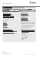
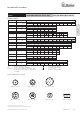
Output circuit Type of connection Cable (isolate unused wires individually before initial start-up)
5000: 1, 2, A, B Signal: 0 V +V 0 Vs
ens
+Vs
ens
A B 0 H
1, 2, 3, 4, 5, 8
5020: 1, A, E, F Core color: WH BN GY PK RD BU GN YE GY PK BU RD shield
Output circuit Type of connection M12 connector, 8-pin
5000: 3, 4, L Signal: 0 V +V A B 0 H
1, 2, 3, 4, 5, 8
5020: 2, H
2)
, L Pin: 1 2 3 4 5 6 7 8 PH
1)
Output circuit Type of connection M12 connector, 5-pin
5000: P, R Signal: 0 V +V A B 0 H
1, 2, 3, 4, 5, 8
5020: R Pin: 1 2 3 4 5 PH
1)
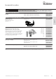
Output circuit Type of connection M23 connector, 12-pin
5000: 7, 8, M Signal: 0 V +V 0 Vs
ens
+Vs
ens
A B 0 H
1, 2, 3, 4, 5, 8
5020: 4, M Pin: 10 12 11 2 5 6 8 1 3 4 PH
1)
Output circuit Type of connection MIL connector, 7-pin
5000: W Signal: 0 V +V +Vs
ens
A B 0 H
1, 3, 4, 5, 8
5020: 6 Pin: F D E A B C G
Output circuit Type of connection MIL connector, 10-pin
5000: Y Signal: 0 V +V +Vs
ens
A B 0 H
1, 2, 3, 4, 5, 8
5020: 7 Pin: F D E A G B H C I J
Output circuit Type of connection MIL connector, 6-pin
5000: 9 Signal: 0 V +V A B 0 H
1, 3, 4, 5, 8
Pin: A B E D C
Output circuit Type of connection Sub-D connector, 9-pin
5000: N Signal: 0 V +V A B 0 H
1, 2, 3, 4, 5, 8
5020: N Pin: 9 5 1 6 2 7 3 8 PH
1)
1) PH = shield is attached to connector housing.
2) With type of connection H shield is not attached to connector housing.
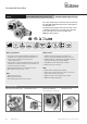
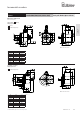
Terminal assignment
MIL connector, 10-pin MIL connector, 6-pinMIL connector, 7-pin Sub-D connector, 9-pin
Top view of mating side, male contact base
M12 connector, 8-pinM12 connector, 5-pin M23 connector, 12-pin
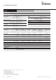
+V: Encoder power supply +V DC
0 V: Encoder power supply ground GND (0 V)
0 Vsens / +Vsens: Using the sensor outputs of the encoder, the voltage
present can be measured and if necessary increased
accordingly.
A, : Incremental output channel A
B, : Incremental output channel B
0, : Reference signal
PH H: Plug connector housing (shield)
Push-pull / RS422 / Open collector
Standard
optical Sendix 5000 / 5020 (shaft / hollow shaft)