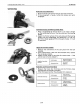
5 BRAKES B1700·B2100·B2400 WSM,11770 [2] BRAKE ASSEMBLY DISASSEMBLING AND ASSEMBLING (1) Separating Rear Axle Case with Brake Assembly Drain the Transmission Fluid 1. 2. 3. 4. Place oi I pans underneath the transmission case. Remove the four drain plugs (1). Drain the transmission oil. Reinstall the four drain plugs (1). (When refilling) • Fill up from filling port after removing plug (2) until reaching the gauge (3). • After running the engine for few minutes, stop it and check the oil level again.
5 BRAKES 81700·82100·82400 WSM, 11770 RearWheel 1. 2. 3. 4. Place a jack under the transmission case. Loosen the rear wheel cotter (1) setting bolt and nut. Take out the wheel hub pi n (2). Take out the rear wheel. l1li IMPORTANT 48 When re-fitting or adjusting a wheel, tighten the bolts to the following torques then recheck after driving the tractor 200 m (200 yards) and there after daily check service.
5 BRAKES B1700·B2100·B2400 WSM,11770 57TGear 1. Remove the external snap ring (3) and remove the bearing (2). 2. Draw out the 57T gear (1) from the rear axle (4). (1) Gear (2) Bearing (3) External Snap Ring (4) Rear Axle (2) Disassembling Brake Assembly Brake Assembly 1. Remove the internal snap ring (1). 2. Remove the brake shaft (2) with brake discs. (When reassembling) .. When installing the internal snap ring (1) to rear axle case (3) as shown in the figure left. ..
5 BRAKES B1700·B21 00·B2400 WSM, 11770 SERVICING Brake Cam Lever Movement 1. Move the brake cam lever by hand to check the movement. 2. If the movement is heavy, refine the brake cam with sandpaper. B177P177 Cam Plate Flatness and Bearing HolderWear 1. Place a straightedge of 150 mm (5.91 in.) or more in length on the contacting surface of the cam plate and the bearing holder. 2. Inspect the friction surface of the cam plate and the bearing holder with the straightedge, and determine if a 0.30 mm (0.
MECHANISM CONTENTS [1] STRUCTURE [2] FRONT WHEEL ALIGNMENT 6-M1 6-M2
6 FRONT AXLE B1700·B21 00'B2400 WSM, 11770 [1] STRUCTURE B177F601 (1) (2) (3) (4) (5) (6) Bevel Gear Case Bevel Gear Differential Yoke Shaft Front Axle Case Differential Case Differential Pinion (7) (8) (9) (10) (11 ) (12) (13) (14) (15) (16) (17) (18) Spiral Bevel Gear Collar Front Axle Bracket, Front Axle Flange Axle Collar The front axle of the 4WD is constructed as shown above.
6 FRONT AXLE B1700·B21 00·B2400 WSM, 11770 [2] FRONT WHEEL ALIGNMENT forward directions. This arrangement is referred to as the Front Wheel Alignment. To assure smooth mobility or maneuverability and enhance stable and straight running, the front wheels are mounted at an angle to the right, left and [Kingpin Angle] [Camber] a //i C045F053 C045F051 The front wheels are tilted from the vertical as viewed from the front, upper wheels are spreader than lower ones.
BGRVICING CONTENTS TROUBLESHOOTING SERVICING SPECIFICATIONS TIGHTENING TORQUES CHECKING.
6 FRONT AXLE B1700·B21 00·B2400 WSM, 11770 TROUBLESHOOTING Probable Cause Symptom Front Wheels Wander to Right or Left Front Wheels Can Not Be Driven Reference Page pressure uneven • Tire Improper • alignment)toe-in adjustment (improper Adjust Adjust G-35 6-53 • Clearance between front axle case boss and front axle bracket (front, rear) excessive Front axle rocki ng force too small Front wheel sway excessive Tie-rod end loose Air sucked in power steering circuit Replace 6-511 • • • • Adjust Rep
6 FRONT AXLE B1700·B2100·B2400 WSM,11770 SERVICING SPECIFICATIONS Item Factory Specification Allowable Limit 1 to 10 mm 0.04 to 0.39 in. - Less than 5 mm 0.20 in. - 49.0 to 117.7 N 5.0 to 12.0 kgf 11.0 to 26.51bs - Front Wheel Alignment Toe-in Front Wheel Axial Sway Front Axle Rocking Force Differential Case, Differential Case Cover to differential Side Gear Clearance 0.040 to 0.082 mm . 0.00157 to 0.00323 in. 0.17 mm 0.0067 in. Differential Case 1.0. 26.000to26.021 mm 1.02362 to 1.
6 FRONT AXLE B1700·B2100·B2400 WSM,11770 (Continued) Item Factory Specification Allowable Limit Front Axle Case Boss (Front) O.D. 49.920 to 49.945 mm 1.96535 to 1.96634 in. - Front Axle Bracket (Front) I.D. 50.150 to 50.200 mm 1.97441 to 1.97638 in. - Front Axle Case Boss (Rear) O.D. 64.91 Oto 64.940 mm 2.55551 to 2.55669 in. - Front Axle Bracket (Rear) I.D. 65.150 to 65.200 mm 2.56496 to 2.56693 in.
6 FRONT AXLE 81700·82100'82400 WSM,11770 Axial Sway of Front Wheel 1. 2. 3. 4. Jack up the front side of tractor. Set a dial gauge on the outside of rim. Turn the front wheel slowly and read the runout of rim. If the runout exceeds the factory specifications, check the bearing, rim, and front wheel hub. Axial sway of front wheel Factory spec. Lessthan 5.0 mm 0.20 in. Front Axle Rocking Force 1. 2. 3. 4. Jack up the front side of tractor. Set a spring balance to the front axle flange.
6 FRONT AXLE B1700·B2100·B2400 WSM,11770 DISASSEMBLING AND ASSEMBLING (1) Separating Front Axle Draining FrontAxle Case Oil t. 1. Place oil pans underneath the front axle case. 2. Remove both right and left drain plugs (3) and filling plug (2) to drain the oil. 3. Remove the right and left breather plugs. 4. After draining, reinstall the drain plugs (3). 5. Fi II with new oil up to the upper notch on the dipstick. 6. After filling, reinstall the filling plug and breather plugs. 3.
6 FRONT AXLE B1700·B2100·B2400 WSM,11770 Drag Link 1. Steer the front wheels to the left. 2. Remove the slotted nut and disconnect the drag link (2) from the knuckle arm (1). II IMPORTANT • After tightening the slotted nut to the specified torque, install the cotter pin as shown in the figure left. Tightening torque 17.7 to 34.3 N'm 1.8 to 3.5 kgf'm 13.0 to 25.3 ft-Ibs Slotted nut (2) Drag Link (1) Knuckle Arm 030F129 Front Axle 1.
6 FRONT AXLE B1700·B2100·B2400 WSM,11770 Bevel Gear Case, Axle Flange and Front Gear Case 1. 2. 3. 4. 5. Remove the knuckle arm (Left side). Remove the axle flange (1) mounting screw~. Remove the external snap ring (2). Remove the bevel gear case (3) from front gear case (7). Remove the bevel gear shaft (4) and ball bearing.
6 FRONT AXLE B1700·B2100·B2400 WSM,11770 Bevel Gear Case Gears 1. Remove the internal snap ring (1). 2. Take out the bevel gears (4), (5) with ball bearings (3), (6), and shims (2). (When reassembling) • Install the shims (2) to their original position. (Reference) • Thickness of adjusting shims: 0.8 mm (0.031 in.) 1.2 mm (0.047 in.) 1.0 mm (0.039 in.) (1) (2) (3) (4) Internal Snap Ring Shim Ball Bearing Bevel Gear (5) Bevel Gear (6) Ball Bearing (7) Bevel Gear Case Axle 1. 2. 3. 4.
6 FRONT AXLE B1700·B21 00'B2400 WSM, 11770 Spiral Bevel Pinion Shaft and Differential Gear Assembly 1. Take out the differential yoke shaft (9), (10). 2. Remove the internal snap ring (5). 3. Tap out the spiral bevel pinion shaft (3) by the brass rod and hammer. 4. Take out the differential gear assembly (2), ball bearing (11) and collar (12) from right side of front axle case (1). 5. Remove the stake of lock nut (8), and then remove the lock nut (8). 6. Remove the taper roller bearings (6).
6 FRONT AXLE 81700'82100·82400 WSM,11770 SERVICING Clearance between 'Differential Case (Differential Case Cover) and Differential Side Gear 1. Measure the differential side gear boss 0.0. 2. Measure the differential case bore 1.0. and calculate the clearance. 3. Measure the differential case cover bore 1.0. and calculate the clearance. 4. If the clearance exceeds the allowable limit, replace faulty parts.
6 FRONT AXLE B1700·B2100·B2400 WSM,11770 Turning Force of Spiral Bevel Pinion Shaft 1. Install the spiral bevel pinion shaft assembly to the front axle case. 2. Wind a string around the spiral bevel pinion shaft and attach spring balance to the tip ofthe string. 3. Slowly pull the spring balance in a direction at right angle to the spiral bevel pinion shaft to measure the turning force. 4. If the turning force is not within the factory specifications, adjust with the lock nut. Turning force Factory:>pec.
6 FRONT AXLE B1700·B2100·B2400 WSM,11770 Backlash between 11T Bevel Gear and 16T Bevel Gear 1. Stick a strip of fuse to three spots on the 16T bevel gear (1) with grease. 2. Fix the front axle case, bevel gear case and front gear case. 3. Turn the axle. 4. Remove the bevel gear case from front axle case and measure the thickness of the fuses with an outside micrometer. 5. If the backlash is not within the factory specifications, adjust with shim (3).
MECHANISM· .
7 STEERING B1700·B2100·B2400 WSM,11770 [1] HYDRAULIC CIRCUIT FOR POWER STEERING SYSTEM 5£/min ] [ 1.3 U.S.GPM 1.1Imp.GPM ® © ~ 17£/min ] [ 4.4 U.S.GPM 3.7Imp.GPM 10 r[ 8 11 2 2£/min ] 5.7 U.S.GPM 4.8 Imp.
7 STEERING B1700·B21 00·B2400 WSM,11770 [2] POWER STEERING BODY B177F702 (1) (2) (3) (4) (6) Sector Gear Shaft Balls Ball Nut Worm Shaft Relief Valve (12) (13) (14) (15) Reaction Pistons Centering Springs Gear Case O-Ring (16) (17) (18) (19) 7-M2 Teflon Ring Thrust Races Thrust Needle Bearings Spool (20) (21) (22) (23) Valve Housing Nut Oil Seal Adjusting Screw for Play
7 STEERING B1700·B21 00·B2400 WSM, 11770 [3] OIL FLOW • Neutral Position @@ ++ I 5 (A) From Pump (Through Flow Priority Valve) (B) To HST Unit (HST Type) or Transmission Case (Manual Transmission Type) (1 ) (2) (3) (4) Sector Gear Shaft Ball Nut Worm Shaft Reaction Pistons (5) Centering Spring (6) Valve Housing (7) Spool [=:J Low Pressure B177F703 pressures on the right and left cylinder chambers. And the ball nut (2) and sector gear shaft (1) do not move. So, the front wheels keep the direction.
7 STEERING B1700·B2100·B2400 WSM,11770 II Right Turning (1 ) (2) (3) (4) (5) (6) (7) (8) (9) (10) (A) (B) (a) (b) Sector Gear Shaft Ball Nut Worm Shaft Centering Spring Reaction Piston Valve Housing Spool Thrust Race Ball Relief Valve Chamber "A" Chamber "B" Port" a" Port "b" 7 High Pressure I=:::J Low Pressure B177F705 1. When the steering wheel is turned clockwise, the worm shaft (3) is also turned.
7 STEERING B1700·B2100·B2400 WSM,11770 II Operation of Relief Valve High Pressure B177F706 (1) Adjusting Screw (2) Spring (3) Poppet This power steeri ng is eq u i pped with a direct-acting relief valve to restrict the maximum pressure in the hydraulic circuit and to prevent breakage of the hydraulic equipment.
SGRVICING " CONTENTS TROUBLESHOOTING SERVICING SPECIFICATIONS TIGHTENING TORQUES CHECKING, DISASSEMBLING AND SERVICING CHECKING [1] SEPARATING POWER STEERING BODY [2] POWER STEERING BODY DISASSEMBLING AND ASSEMBLING SERVICING 7-51 7-52 7-53 .
7 STEERING 81700·82100·82400 WSM,11770 TROUBLESHOOTING Probable Cause Symptom Excessive Steering Wheel Play Tractor Pulls to Right or Left Front Wheels Vibration Hard Steering Low Operating Pressure Steering Wheel Does Not Return to Neutral Position Noise Reference Page • Backlash between sector gear shaft and ball nut too large Steering linkage worn Sector gear shaft worn Adjust 7-S13 Replace Replace - Tire pressure uneven • Steering play too small •.
7 STEERING B1700·B2100·B2400 WSM,11770 SERVICING SPECIFICATIONS Item Steeri ng Wheel Play Operation Force Condition: • Engine Speed Approx. 2600 rpm Relief Valve Setting Pressure Condition: • Engine Speed: Approx. 2600 rpm • Oil Temperature: 45 to 55°C 113 to 131°F Steering Gear Boxto Ball Nut Clearance Factory Specification Allowable Limit 5.0 to 30.0 mm 0.2 to 1.2 in. - Less than 49 N 5.0 kgf. 11 Ibs. - 11.28to 11.77 MPa 115 to 120 kgf/cm 2 1636 to 1707 psi - 0.035 to 0.079 mm 0.
7 STEERING 61700·62100·62400 WSM,11770 (Continued) Factory Specification Allowable Limit Clearance 0.040 to 0.074 mm 0.00158toO.00291 in. 0.20 mm 0.0078 in. Sector Gear Shaft 0.0. 27.987 to 28.000 mm 1.10185 to 1.10236 in. - Steering Gear Box 1.0. 28.040 to 28.061 mm 1.10394to 1.10476in. - Less than 0.30 mm 0.0118 in. - Less than 0.78 N·m 0.08 kgf·m 0.58 ft-Ibs.
7 STEERING B1700·B2100·B2400 WSM,11770 CHECKING, DISASSEMBLING AND SERVICING CHECKING _IMPORTANT • Use only the transmission fluid (See page S.G-3), in no case use mixture of oils of different brands. • Do not disassemble the hydraulic pump and power steering needlessly. • After installing or reassembling the power steering hydraulic components, be sure to bleed air.
7 STEERING B1700·B21 00·B2400 WSM, 11770 [1] SEPARATING POWER STEERING BODY Hood and Side Cover 1. Open the hood (1) from the front and remove the spring lock pin and remove hood with hood rod for keeping it open. 2. Remove the front grille (4). 3. Remove the right and left side cover (2), (3). (3) Side Cover LH (4) Front Grille (1) Hood (2) Side Cover RH Battery 1. Disconnect the battery cords (1) and dismount the battery (2).
7 STEERING B1700·B21 00'B2400 WSM, 11770 Fuel Tank 1. Disconnect the fuel hose between fuel filter and fuel tank at the fuel filter side, then drain fuel completely. 2. Remove the fuel tank frame stay (1). 3. Disconnect the regulator and hazard unit connectors, and remove the lead wire for fuel gauge. 4. Disconnect the fuse box (4). 5. Dismount the overflow hoses (5) of fuel line. 6. Remove the tank flame (2) with fuel tank (3).
7 STEERING B1700·B2100·B2400 WSM,11770 Power Steering Assembly 1. Remove the power steering delivery pipe (1) and return pipe (2). 2. Disconnect the speed set rod (HST type) and parking brake rod. 3. Remove the power steering assembly (3) from the center frame. (When reassembling) B177P069 (1) Power Steering Delivery Pipe (2) Power Steering Return Pipe (3) Power Steering Assem bly Flare nut (PS delivery, return pipe) 29.4 to 39.2 N'm 3.0 to 4.0 kgf'm 21.7 to 28.
7 STEERING B1700·B2100·B2400 WSM,11770 Valve Assembly 1. Install the four top cover mounting nuts to the stud bolt temporaly by hand. 2. Remove the stake of nut (1), then remove it. 3. Remove the valve assembly. Set the worm shaft horizontally to remove each part easily. (When reassembling) IMPORTANT Lightly tighten the nut (1) by hand, and while holding the worm shaft (9), tighten with a wrench. After tightening, loosen the nut approx. 0.17 rad. (10°), and stake the nut (1) with a pin punch.
7 STEERING B1700·B2100·B2400 WSM,11770 Side Cover 1. Remove the lock nut (2) on the adjusting screw. 2. Remove the side cover mounting screws. 3. Turn the adjusting screw (3) clockwise to remove the side cover (1). (When reassembling) .. Apply grease to the O-ring . .. Apply grease to the ring groove, before mounting the U-seal on it. .. Direct the lip of U-seal inward, as shown in the figure . .. Replace the lock nut with a new one, and after adjusting the backlash between sector gear .
7 STEERING B1700·B21 00'B2400 WSM, 11770 Adjuster of Sector Gear Shaft 1. Remove the stake and adjuster (2). (1) Adjusting Screw (2) Adjuster (3) Sector Gear Shaft B177F711 (When reassembling) .. Apply grease to the head of adjuster. Snap Ring 1. Remove the snap ring (1) which retains the end cover (2). (When reassembling) III NOTE .. Direct the blunt edge side of the snap ring (1) to the end cover (2). (2) End Cover End Cover and Ball Nut Assembly 1.
7 STEERING 81700·82100·B2400 WSM,11770 Seal Ring on Ball Nut 1. Cut the seal ri ng with a knife and remove it. 2. Remove the O-ring inside the teflon ring. (When reassembling) • Apply grease to the ring groove. • Replace the seal rings with new ones. • Stretch the teflon ring by hand, install it on the ball nut, and press it so that it is restored to its original form. (1) Ball Nut Bl77P209 Seal Rings on Gear Box 1. Remove the seal ring (1). 2. Remove the seal ring (2).
7 STEERING B1700·B21 00·B2400 WSM, 11770 Axial Play of Ball Nut Assembly 1. Secure the ball nut assembly in a vise. 2. Set a dial indicator with its finger on the worm shaft of the ball nut assembly. 3. Move the worm shaft axially and measure the play. 4. If the play exceeds the allowable limit, replace the ball nut assembly. OtoO.12 mm Factory spec. oto 0.0047 in. Allowable limit 0.100 mm 0.00394 in. Axial play of ball nut assembly Clearance between Valve Housing and Spool 1.
7 STEERING 81700'82100·82400 WSM,11770 Clearance between Sector Gear Shaft and Side Cover 1. Measure the sector gear shaft O. D. with an outside micrometer and side cover I.D. with a cylinder gauge, and calculate the clearance. 2. If the clearance exceeds the allowable limit, replace the defective parts. Clearance between side cover and sector gear shaft Factory spec. 0.005 to 0.034 mm 0.00020 to 0.00206 in. Allowable limit 0.1 mm 0.0039 in. Sector gear shaft 0.0. Factory spec. 27.987to 28.
\,
MECHANISM , CONTENTS [1] [2] [3] [4] [5] [6] [7] [8] [9] HYDRAULIC CIRCUIT HYDRAULIC PUMP FLOW PRIORITY VALVE POSITION CONTROL VALVE FEEDBACK LINKAGE FOR POSITION CONTROL RELIEF VALVE HYDRAULIC CYLINDER HYDRAULIC BLOCK TYPE OUTLET REAR HYDRAULIC OUTLET 8-M1 8-M3 8-M3 8-M4 8-MS 8-M6 8-M7 8-M8 8-M8
8 HYDRAU Lie SYSTEM 81700·82100·82400 WSM, 11770 [1] HYDRAULIC CIRCUIT II MANUAL TRANSMISSION (1) (2) (3) (4) (5) (6) (7) (8) (9) (10) 5 8177F801 I I ~-~ ----I~~ Oil Flow in Neutral State 8177F802 8-M1 Position Control Valve Rear Hydraulic Outlet Power Steering Flow Priority Valve Oil Strainer Hydraulic 810ck Type Outlet Hydraulic Pump Hydraulic Cylinder Lowering Speed Adjusting Valve Relief Valve
8 HYDRAULIC SYSTEM B1700'B21 00·B2400 WSM, 11770 • HYDROSTATIC TRANSMISSION (1) Position Control valve (2) Oil Filter (3) Hydrostatic Transmission (HST) (4) Power Steering (5) Flow Priority Valve (6) Oil Cooler (7) Rear Hydraulic Outlet (8) Oil Strainer (9) Hydraulic Block Type Outlet (10) Hydraulic Pum p (11) Hydraulic Cylinder (12) Lowering Speed Adjusting Valve (13) Relief Valve Bl77F803 :--------{ :~ I I I \-, I ' _ lb__ ~~, 5 I 10 r------------i i i , ~. - -.......
~ ~ - - - - - ~ - ~~- 8 HYDRAU Lie SYSTEM B1700·B2100·B2400 WSM,11770 • Hydraulic System The hydraulic system of these tractors are composed of a hydraulic pump, hydraulic block type outlet, control valve, hydraulic cylinder, hydraulic oil filter and other components. This system has the following functions. 1. Position control of the rear implement connected to the 3-poi nt hitch. 2.
8 HYDRAU L1C SYSTEM B1700·B2100·B2400 WSM,11770 [4] POSITION CONTROL VALVE This position control valve is located under the hydraulic cylinder block. ,)0 II Neutral Oil forced into the control valve through the P port pushes open the unload poppet (4) and then returns to the transmission case through the T1 port. Oil behind the unload poppet (4) returns to the transmission case through the spool (3) and the T3 port.
8 HYDRAU Lie SYSTEM B1700·B2100·B2400 WSM,11770 II1II Down When the control lever is moved to DOWN position, the spool (4) is move to the left, and the poppet 2 (2) is also move to the left by the lever (1). Oil in the hydraulic cylinder. is forced out to the transmission case through the T2 port by the weight ofthe implement, causing the implement to lower. Oil forced into the control valve through the P port pushes open the unload poppet (5) and returns to the transmission case through the T1 port.
8 HYDRAULIC SYSTEM B1700·B2100·B2400 WSM,11770 [6] RELIEF VALVE 2 4 3 From Hydraulic Pump - I I From Hydraulic _ Pump T Port (To Transmission Case) I I [- I + To Position Control Valve B177F811 The Three point hydraulic system circuit has a relief valve to restrict the maximum pressure in the circuit. The relief valve is located top of the hydraulic cylinder body. The relief valve is of the guide piston type with damping effect.
8 HYDRAU Lie SYSTEM B1700·B2100·B2400 WSM,11770 [7] HYDRAULIC CYLINDER 11 B177FB12 (1) Lowering Speed Adjusting Shaft (2) Lowering Speed Adjusting Valve (3) Hydraulic Cylinder (4) Relief Valve (5) Hydraulic Arm (6) Piston (7) a-ring (8) Back-up Ring (9) Hydraulic Rod The main components of the hydraulic cylinder are shown in the figure above. While the lift arm (11) is rising, oil from the hydraulic pump flows into the hydraulic cylinder through the position control valve (10).
8 HYDRAULIC SYSTEM B1700·B2100·B2400 WSM,11770 [8] HYDRAULIC BLOCK TYPE OUTLET The hydraulic block type outlet is located at the right hand side ofthe engine. This hydraulic block type outlet is provided to take power out from the tractor to operate the hydraulic cylinders on the implement, such as front end loader, front blade and so on.
SGRVICING I CONTENTS TROUBLESHOOTING SERVICING SPECIFICATIONS TIGHTENING TORQUES CHECKING. DISASSEMBLING AND SERVICING [1] HYDRAULIC PUMP CHECKING AND ADJUSTING DISASSEMBLING AND ASSEMBLING SERVICING [2] HYDRAULIC CYLINDER ASSEMBLY (HYDRAULIC CYLINDER. POSITION CONTROL VALVE.
8 HYDRAULIC 5Y5TEM B1700·B2100·B2400 WSM,11770 TROUBLESHOOTING Probable Cause Symptom Implement Does Not Rise (No Noise) (Noise) • • • • • • • • • • • • • Control valve broken Control valve improperly adjusted Control valve improperly assembled Relief valve spring damaged 5pool sticks Piston O-ring or cylinder damaged Oil strainer clogged 5uction pipe loosen or broken 5uction pipe connecting hose loosen or broken 5uction pipe O-ring broken Insufficient transmission oil Relief valve setting pressure to
8 HYDRAU lIC SYSTEM 81700·82100·82400 WSM,11770 SERVICING SPECIFICATIONS Factory Specification Item [Hydraulic Pump] Pump Delivery at Engine 2600 rpm, ail Temperature 50°C, 122°F at no pressu re - 18.0.llmin. 4.8 U.S.GPM 4.0Imp.GPM 16.0.llmin. 4.2 U.S. GPM 3.5Imp.GPM Clearance 0.020 to 0.091 mm 0.0008 to 0.0036 in. 0.12 mm 0.0047 in. Gear Shaft a.D. 14.970 to 14.980 mm 0.5894 to 0.5898 in. - Bushing I.D. 15.000to 15.061 mm 0.5906 to 0.5930 in. - Side Plate Thickness 2.48 to 2.50 mm 0.
8 HYDRAU L1C SYSTEM 81700·82100·82400 WSM, 11770 TIGHTENING TORQUES Tightening torques of screws and nuts on the table bellow is especially specified.
8 HYDRAULIC SYSTEM B1700'B2100'B2400 WSM,11770 CHECKING, DISASSEMBLING AND SERVICING [1] HYDRAULIC PUMP CHECKING AND ADJUSTING Flowmeter Connecting and Test Preparation • IMPORTANT .. When using a flowmeter other than KUBOTA specified flowmeter (Code No.: 07916-52791), be sure to use the instructions with that flowmeter. .. In this hook-up, there is no relief valve. Therefore while testing, do not close the flowmeter loading valve completely. B177F815 1. Disconnect the accelerator rod (6). 2.
8 HYDRAULIC SYSTEM 81700·82100·82400 WSM,11770 Pump Test III NOTE .. Before pump testing, perform the Flowmeter Connecting and Test Preparation. (See page 8-54). 1. 2. 3. 4. Open the loading valve completely. Start the engine and set at approx. 2600 rpm. Read and note the pump delivery at no pressure. Slowly close the loading valve to increase pressure approx. 14.7 MPa (150 kgf/cm 2 , 2133 psi). 5. Read and note the pump flow at rated pressure. 6. Open the loading valve and stop the engine. 7.
8 HYDRAU Lie SYSTEM 81700'82100·82400 WSM, 11770 Removing Hydraulic Pump 1. 2. 3. 4. 5. Disconnect the accelerator rod (1). Remove the fuel cut off solenoid (2). Remove the fuel filter bracket (4) mounting screws. Remove the flow priority valve (3). Disconnect the suction hose (5) and remove the hydraulic pump (6). (When reassembling) • Apply grease to O-ring and take care not to damage it. • Apply liquid gasket (Three Bond 1208D or equivalent) to the engine stop solenoid gasket.
8 HYDRAULIC SYSTEM 81700·82100·82400 WSM, 11770 Side Plate and Gear 1. Remove the side plate (4). 2. Remove the drive gear (2) and driven gear (3) from the casing (1). (When reassembling) • Install the side plate, noting its location and direction . • Install the gears, noting its direction. (1) Casing (2) Drive Gear (3) Driven Gear (4) Side Plate 8177P224 SERVICING Clearance between Tip of Gear Tooth and Casing 1. Measure the gear a.D. with an outside micrometer. 2. Measure the casing I.D.
8 HYDRAU L1C SYSTEM 81700'82100·82400 WSM,11770 [2] HYDRAULIC CYLINDER ASSEMBLY (HYDRAULIC CYLINDER, POSITION CONTROL VALVE, RELIEF VALVE AND ETC) CHECKING AND ADJUSTING Relief Valve Setting Pressure 1. Remove the seat under cover. 2. Remove the plug from front of hydraulic cylinder block. 3. Install the adaptor 58. Then connect the cable and pressure gauge to adaptor 58. 4. Remove the position control lever stopper. 5. Start the engine and set at maximum speed. 6.
8 HYDRAULIC SYSTEM B1700·B2100·B2400 WSM,11770 DISASSEMBLING AND ASSEMBLING (1) Separating Hydraulic Cylinder Assembly Seat, Seat Rail, Seat Stay and Seat Under Cover 1. Remove the seat (1) and lowering speed adjusting knob (2). 2. Remove the tool box (5) and seat under cover (3). 3. Remove the seat stay (6) and seat rail (4) as a unit. (1) Seat (2) Lowering Speed Adjusting Knob (3) Seat Under Cover (4) Seat Rail (5) Tool Box (6) Seat Stay Hydraulic Cylinder Assembly 1. 2. 3. 4.
8 HYDRAU Lie SYSTEM 81700·82100'82400 WSM,11770 (2) Disassembling Hydraulic Cylinder Assembly Position Control Valve 1. Remove the position control valve mounting screws, and remove the position control valve(l). (When reassembling) o Take care not to damage the O-rings. Tightening torque Position control valve mounting screws 23.6 to 27.4 N'm 2.4 to 2.8 kgf·m 17.4 to 20.2 ft-Ibs (1) Position Control Valve Lift Arm, Hydraulic Arm Shaft and Hydraulic Arm 1. Remove the position control feedback rod (4).
8 HYDRAULIC SYSTEM 81700·82100'82400 WSM,11770 Lowering Speed Adjusting Valve 1. Remove the lowering speed adjusting valve body (2) with the lowering speed adjusting shaft (1). 2. Draw out the poppet (3) and spring (4). (When reassembling) .. Take care not to damage the O-rings. (1) Lowering Speed Adjusting Shaft (2) Lowering Speed Adjusting Valve 80dy (3) Poppet (4) Spring 8177P242 Relief Valve 1. Remove the plug (1), and draw out the shim (2), spring (3), poppet (4) and the valve seat (5).
8 HYDRAU Lie SYSTEM 81700·82100·82400 WSM, 11770 Poppet 2 and Unload Poppet 1. Remove the plug 3 (4), and draw out the poppet 2 (3). 2. Remove the plug 2 (2), and draw out the unload poppet (1). 2 (When reassembling) • Take care not to damage the O-ring. Plug 3 39.2 to 58.8 N'm 4.0 to 6.0 kgf·m 28.9 to 43.4 ft-Ibs Plug 2 29.4 to 49.0 N'm 3.0 to 5.0 kgf'm 21.7 to 36.2 ft-Ibs Tightening torque (1) Unload Poppet (2) Plug 2 (3) Poppet 2 (4) Plug 3 Poppet 1 1.
8 HYDRAU L1C SYSTEM B1700·B21 00·B2400 WSM, 11770 SERVICING Hydraulic Cylinder Bore 1. Check the cylinder internal surface for scoring or damage. 2. Measure the cylinder 1.0. with a cylinder gauge. 3. If the measurement exceeds the allowable limit, replace the hydraulic cylinder block. Factory spec. 70.05 to 70.10 mm 2.7579 to 2.7598 in. Allowable limit 70.15 mm 2.7618 in. Cylinder I.D. B177P243 Clearance between Hydraulic Arm Shaft and Bushing 1. Measure the hydraulic arm shaft 0.0.
MECHANISM CONTENTS [1] WIRING DIAGRAM AND ELECTRICAL CIRCUIT [2] STARTING SYSTEM (1) Starter (2) Glow Plug (3) Safety Switch [3] ENGINE KEY SWITCH SHUT·OFF SYSTEM (1) Fuel Cut Off Solenoid [4] CHARGING SYSTEM (1) AC Dynamo (2) Regulator (3) Alternator (4) IC Regulator [5] LIGHTING SYSTEM (1) Head Light (2) Hazard Light [6] EASY CHECKER (1) Indication Items (2) Low Engine Oil Pressure [7] GAUGE (1) Fuel Quantity (2) Coolant Temperature 9-M1 9-M5 9-M6 9-M7 9-M7 9-M8 9-M8 9-M9 9-M11 9-M 11 9-M 12 9-M 12 9-M1
9 ELECTRICAL SYSTEM B1700·B2100·B2400 WSM,11770 [1] WIRING DIAGRAM AND ELECTRICAL CIRCUIT • With AC Dynamo • Main Switch ~ Key Position OFF ON PREHEAT START • Combination Switch • Color of Wiring Head Light Switch 30 •... AC 19 ~ OFF ... -... -... -... - 50 - - ON Hazard Light Switch T 81 •... 1 ~ 1 ... ... OFF R R.H. Hazard L.H. Hazard Light Light R L -...
9 ELECTRICAL SYSTEM B1700·B2100·B2400 WSM,11770 • With AC Dynamo • Color of Wiring .. .. _--- .. __ .... - Yellow Or Orange RB B ...... - ......
9 ELECTRICAL SYSTEM 81700·B2100·B2400 WSM, 11770 • With Alternator • Main Switch ~ Key Position OFF ON PREHEAT START • Combination Switch • Color of Wiring Head Light Switch 30 AC 19 50 •- - - - - - - ~ T B1 •- OFF ON - Hazard Light Switch ~ 1 ...- 1 B2 L R .- ---e • OFF - 2 • W ---_ .. _------- White Or ----------- R ------------- Red WR ----------- L ------------- Blue RL White / Red GW ----------- Green/White WY ----------- White/Yellow RG -----oo..
9 ELECTRICAL SYSTEM B1700-B2100-B2400 WSM,11770 • With Alternator • Color of Wiring W -----------_ .. White R -----------_ .. L -------_ .....-- Red Blue Y -- .. -_ .. _------ Yellow Or B ------------- Black WR ----------- White/Red G ------------- Green WY .... _------- RB Orange ----------- Red / Black RW ----------- Red /White ----_ .. _---- White/Yellow RL ----------- Red / Blue RG ----------- Red / Green RY --_ .. ------- Red/Yellow BW ...........
9 ELECTRICAL SYSTEM B1700·82100·82400 WSM,11770 [2] STARTING SYSTEM Main Switch Table 30 OFF AC 19 50 • ON PREHEAT START At the "START" Position At the "PREHEAT" Position "-~-1 5A f - - - - 15Af----10AI---- ® T T 1(J) I(J) I -L -L B177F906 B177F905 (1) Main Switch (2) Safety Switches (3) Slow Blow Fuse (4) Starter Motor (5) Glow Plugs (6) Pre-heat Indicator Lamp When the main switch (1) is turned to the PREHEAT position, the terminal 30 is connected to the terminals 19 and AC.
9 ELECTRICAL SYSTEM B1700·B2100·B2400 WSM,11770 (1) Starter B177F907 (1) Front Bracket (2) Lever (3) Magnetic Switch (7) Overrunning Clutch (8) Internal Gear (9) Gear Shaft (4) Pinion Gear (5) Gasket (6) Armature Shaft The starter is a reduction type. The reduction system is used planetary gears, and the speed of gear shaft (9) is reduced to approximately one fifth of the armature shaft (6).
9 ELECTRICAL SYSTEM 81700'82100·82400 WSM,11770 (2) Glow Plug 1200 1 ® 1 1000 a BOO 10 20 © C140F060 This plug is a two-material type QGS (Quick Glow System) for quick temperature rise, and has selfcontrolling function as well as excellent durability. The heater (4) connected in series to the heater (3), which also functions as the resistor, is incorporated in the sheath tube (1) of the super glow pi ug.
9 ELECTRICAL SYSTEM B1700·B2100·B2400 WSM,11770 [3] ENGINE KEY SWITCH SHUT-OFF SYSTEM CD r-----j 5A f - - - - - - - - , T ® ®: 1.7 ...
9 ELECTRICAL SYSTEM B1700·B2100·B2400 WSM,11770 [4] CHARGING SYSTEM II With AC Dynamo ® T® (J) I 1.7 ..L W B177F910 (1) Main switch (2) Fuse (5) Battery (6) AC Dynamo (3) Slow Blow Fuse (4) Regulator The charging system supplies electric power for various electrical devices and also charges the battery while the engine runs. It consists of a AC dynamo and a regulator.
9 ELECTRICAL SYSTEM B1700·B2100·B2400 WSM,11770 • With Alternator , - - - - - - 1 iDA CD 30 t------------,---------, V""C 1.7® w Off 50 'A 'A ''I " =I 0'I ..L B177F911 (1) Main Switch (2) Fuse (3) Charge Lamp (4) Slow Blow Fuse (5) Alternator (6) IC Regulator The charging system supplies electric power for various electrical devices and also charges the battery while the engine runs. This alternator has IC regulator.
9 ELECTRICAL SYSTEM B1700·B2100·B2400 WSM,11770 (1) AC Dynamo This dynamo is an 8-8 pole rotating magnet type generator. It is simple in construction, consisting of a stator and rotor. The rotor is made up of eight permanent magnet pole pieces assembled on a shaft and rotates on the center of the stator around which eight electromagnetic coils are provided for. This dynamo produces higher voltage in slow speed rotation, and charges electric current to the battery during engine idling.
9 ELECTRICAL SYSTEM B1700·B2100·B2400 WSM,11770 (3) Alternator A compact alternator with an IC regulator is used, having the following characteristics: • Approxi mately 26% lighter and 17% smaller than a standard alternator. • Cooling performance and safety have been improved by combining the cooling fan with the rotor and incorporating the fan/rotor unit inside the alternator. • IC regulator is fitted inside the alternator.
9 ELECTRICAL SYSTEM B1700·B2100·B2400 WSM,11770 [5] LIGHTING SYSTEM CD ®1 0 A l - - - - - , . - - - - - - - - - - - - - - - . . . , . - - - - , - - - - r - l 1 5 A r - - - - - - - - - - - - - - - - - - - - - - - - --_---, ® 5A 1-----, L R 81 T 1 --f @ I I I I I I I I I : ~_ I I I I I I I I I I -l B177F912 (1) (2) (3) (4) (5) (6) Fuse Fuse Fuse Main Switch Hazard Unit Combination Switch (7) (8) (9) (10) (11 ) Slow Blow Fuse Pre-heat Indicator Lamp Battery Charge Lamp L.H. Hazard Lamp (12) R.
9 ELECTRICAL SYSTEM B1700·B2100·B2400 WSM,11770 (1) Head Light L.H. Head Light R.H. Head Light Battery or Charging System L.H. Tail Light R.H. Tail Light B177F913 The light switch, which forms a combination switch with the hazard switch, has two position; OFF and ON. Current passes through the light circuit as shown in the figure above. (2) Hazard Light L.H. Hazard Light L.H. Hazard Lamp Battery or Charging 1--...... Fuse System 1-----' Hazard Unit R.H. Hazard Light R.H.
9 ELECTRICAL SYSTEM B1700·B21 00·B2400 WSM, 11770 [6] EASY CH ECKER To check the conditions of tractor easily before and during operation, easy checker combination of lamps on the easy checker board is provided. (1) Indication Items 1001 Pre-heat Indicator Lamp When the key switch is in the "Preheat" position, the pre-heat indicator lamp illuminates. It:31 Charge Lamp When the charging system is not functioning properly, this lamp illuminates.
9 ELECTRICAL SYSTEM B1700·B2100·B2400 WSM,11770 [7] GAUGE ® lOA I-----~----, The fuel quantity and coolant temperature are indicated by the ammeters. The ammeters indicate each amperate flowing through the fuel level sensor (7) for the fuel quantity detection and through the coolant temperature sensor (8) for the coolant temperature detection.
SERVICING CONTENTS TROUBLESHOOTING SERVICING SPECIFICATIONS CHECKING.
9 ELECTRICAL SYSTEM B1700·B2100·B2400 WSM,11770 TROUBLESHOOTING Probable Cause Symptom All Electrical Equipments Do Not Operate Fuse Blown Frequently .... Solution Reference Page Battery discharged or defective Battery positive cable disconnected or improperly connected .. Battery negative cable disconnected or improperly connected .. Slow blow fuse blown Recharge or Replace Repair or Replace 9-54 9-54 Repair or Replace 9-54 Replace - .. Short-circuited Repair or Replace - .... ...
9 ELECTRICAL SYSTEM 81700·82100·82400 WSM,11770 ENGINE KEY SWITCH SHUT-OFF SYSTEM Probable Cause Symptom Engine Does Not Stop When Main Switch is Turned Off Engine Does Not Start .... Solution Reference Page Fuse blown (5A) Wiring harness disconnected or improperly connected (between main switch AC terminal and fuel cut off solenoid) .. Fuel cut off solenoid defective Replace Repair or Replace - Replace - .. Fuel cut off solenoid defective Replace - .... Replace Repair or Replace - .... .
9 ELECTRICAL 5Y5TEM B1700'B21 00·B2400 WSM, 11770 Symptom Hazard Light Does Not Light Probable Cause blown (10A) • Fuse Bulb • Wiringblown harness disconnected or improperly • connected (between main switch AC Reference Page Replace Replace Repair or Replace - Replace Replace 9-522 9-520 Replace Repair or Replace - • Hazard unit defective Replace 9-522 • Eng ine oi I pressu re too low Repair engine Replenish - terminal and hazard unit,between hazard unit and combination switch 82 terminal,
9 ELECTRICAL SYSTEM B1700·B2100·B2400 WSM,11770 SERVICING SPECIFICATIONS STARTER MOTOR Item Mica Undercut Factory Specification Allowable Limit 0.5t01.0mm 0.020 to 0.039 in. 0.2mm 0.0079 in. ALTERNATOR Slip Ring O.D. 14.4 mm 0.567 in. 12.8 mm 0.504 in. Brush Length 10.5 mm 0.413 in. 8.4mm 0.331 in. CHECKING, DISASSEMBLING AND SERVICING A CAUTION ..
9 ELECTRICAL SYSTEM 81700·82100·82400 WSM, 11770 Battery Specific Gravity A CAUTION • Keep electrolyte away from eyes, hands and clothes. If you are spattered with it, wash it away completely with water. 1. Check the specific gravity of the electrolyte in each cell with a hydrometer. 2. When the electrolyte temperature differs from that at which the hydrometer was calibrated, correct the specific gravity reading following the formula mentioned in (Reference) below. 3.
9 ELECTRICAL SYSTEM B1700·B21 00·B2400 WSM, 11770 SERVICING Recharging Table 1 [with AC Dynamo] Tractor Model Battery Type Volts (V) Capacity at 5H.R (A.H) B1700 B2100 B2400 50B24L(S)-MF 12 36 Tractor Model Reserve Capacity (min) Cold Cranking Amps Normal Char~ing Rate A) B1700 B2100 B2400 71 390 4.5 A CAUTION When the battery is being activated, hydrogen and oxygen gases in the battery are extremely explosive.
9 ELECTRICAL SYSTEM B1700·B21 00·B2400 WSM, 11770 [2] STARTING SYSTEM CHECKING Main Switch 1. Remove the panel board, and remove the main switch. 2. Perform the following checkings 1) to 5). (1) Main Switch Main Switch From Battery Positive -- --7::!:-;c-+--t.-FI---, Terminal 1) Connector Voltage 1. Measure the voltage with a voltmeter across the connector 30 terminal and chassis. 2. If the voltage differs from the battery voltage (11 to 14 V), the wiring harness is faulty.
9 ELECTRICAL SYSTEM n B1700'B2100'B2400 WSM,11770 3) Main Switch Key at ON Position 1. Turn the main switch on. 2. Measure the resistance with an ohmmeter across the 30 terminal and the AC terminal. 3. If 0 ohm is not indicated, the 30 - AC contacts of the main switch are faulty. I Oohm 30 - AC Resista nce B177F920 4) Main Switch Key at PREHEAT Position 1. Turn and hold the main switch key at the PREHEAT position. 2.
9 ELECTRICAL SYSTEM 81700·82100·82400 WSM,11770 r From Main Switch 19 Terminal and Pre-heat Indicator Lamp Glow Plugs ,~ 8177F915 Pre-heating 1) Lead Terminal Voltage 1. Disconnect the wiring lead from the glow plug terminal after· turning the main switch off. 2. Turn the main switch key to the PREHEAT position, and measure the voltage across the lead terminal and the chassis. 3.
9 ELECTRICAL SYSTEM B1700·B2100·B2400 WSM,11770 Motor Test 1. Disconnect the battery negative cable from the battery. 2. Disconnect the battery positive cable and the leads from the starter. 3. Remove the starter from the engine. 4. Connect the jumper lead from the battery positive terminal post to the B terminal (2), and from the B terminal (2) to the Sterminal (1). 5. Connect a jumper lead momentarily between the battery negative terminal post and the M terminal (3). 6.
9 ELECTRICAL SYSTEM B1700·B21 00·B2400 WSM, 11770 Rear Bracket 1. Remove the mou nti ng screws (1). 2. Remove the rear bracket (2). (1) Screw (2) Rear Bracket B177P256 Brush Holder 1. Remove the mounting screws (1). 2. Remove the brush holder (3) from the rear bracket (2). (1) Screw (2) Rear Bracket B177P257 (3) Brush Holder 3 Armature and Yoke 1. Draw out the armature (3), ball (2) and the yoke (1) from the front bracket.
9 ELECTRICAL SYSTEM B1700·B2100·B2400 WSM,11770 SERVICING Staining or Burning of Commutator 1. Check to see if the commutator surface is stained or burnt. 2. If it is burnt, grind off with a fine-grain sandpaper. Mica Undercut (a) (b) -~ ~ =-~. ~ ....:. ". :;"-. ~ (a)- -. CP rp- 1. Check to see the mica undercut. 2. Ifthe mica is less than the allowable limit, correct with a saw blade. As the edge of the segment will be rough, chamfer it. Factory spec. 0.5to 1.0 mm 0.020 to 0.039 in.
9 ELECTRICAL SYSTEM 81700·82100'82400 WSM,11770 [3] ENGINE KEY SWITCH SHUT-OFF SYSTEM CHECKING Fuel Cut Off Solenoid Lead Terminal Voltage Disconnect the connector of fuel cut-off solenoid. Turn the main switch "ON". Measure the voltage with voltmeter across the terminal 3 (red, black) ofthe wiring harness side and the chassis. 4. If the battery voltage (11 to 14 V) is not indicated, the fuse, the main switch or wiring harness are faulty. 1) 1. 2. 3. Voltage Terminal3 (red, black) - chassis Approx.
9 ELECTRICAL SYSTEM B1700'B21 00'B2400 WSM, 11770 [4] CHARGING SYSTEM CHECKING III AC Dynamo Battery Charging Current 1. After starting the engine, disconnect the battery positive cord (+), and connect an ammeter and voltmeter. Then switch on all electrical loads (such as headlights) and measure the charging current. Battery Positive Cord III NOTE .. Connect an ammeter only after starting the engine. ..
The Correct Voltage Output [INCORRECT] 3TBMAF9P020A [CORRECT] Dynamo No-load Voltage 3. Disconnect the lead wires from the dynamo. 4. Start the engine, and check the generating voltage of the d namo. Factory spec.
9 ELECTRICAL SYSTEM B1700'B21 00'B2400 WSM, 11770 II Alternator Output Current 1. Disconnect the connector (2) from the alternator. 2. Connect the leads with the terminals as shown in the figures. 3. Start the engine and switch on all electrical loads (such as head lights). 4. Set the engine speed at approx. 2250 rpm, and measure the output current. 5. If the measurement is less than the factory specification, the alternator is defective.
9 ELECTRICAL SYSTEM B1700·B2100·B2400 WSM,11770 DIASSEMBLING AND ASSEMBLING II AC Dynamo Stator 1. Remove the nut (3) and separate the stator compo (4). 2. Unscrew the screws (1) and remove the stator (2). (1) Screw (2) Stator (3) Nut (4) StatorComp. B177P306 Rotor 2 1. Tap out the shaft (1) from the rotor (3). (When reassembling) .. Take care the direction of the collar (4), the flat side should face to the pulley (2) side.
9 ELECTRICAL SYSTEM B1700·B2100·B2400 WSM,11770 Brush Holder 1. Unscrew the two screws holding the brush holder and remove the brush holder. C144F032 IC Regulator 1. Unscrew the three screws holding the IC regulator (1) and remove it. (1) IC Regulator C144F033 Rectifier 1. Remove the four screws holding the rectifier (1) and the stator lead wires. (1) Rectifier C144F034 Rear End rrame 1. Remove the two nuts and two screws holding the drive end frame and the rear end frame. 2.
9 ELECTRICAL SYSTEM B1700·B21 00·B2400 WSM, 11770 Retainer Plate 1. Remove the screws holding the retainer plate and remove the retainer plate (1). (1) Retainer Plate C144F036 Bearing on the Drive End Side 2 1. Press out the bearing from drive end frame (4) using with press (1) and jig (2). 4 (1) Press (2) Jig (3) Block (4) Drive End Frame C095F149 Bearing atthe Slip Ring Side 1. Lightly secure the rotor (1) with a vise (2) to prevent damage and remove the bearing using with puller (4).
9 ELECTRICAL SYSTEM 81700·82100·82400 WSM,11770 II Alternator Stator 1. Measure the resistance with an ohmmeter across each lead of the stator coi I. 2. If the measurement is not within factory specification, replace it. 3. Check the continuity across each stator coil lead and core with an ohmmeter. 4. If infinity is not indicated, replace it. Resistance Factory spec. Less than 1.0 ohms 0109F317 Rotor 1. Measure the resistance across the slip rings. 2.
9 ELECTRICAL SYSTEM 81700'82100·82400 WSM,11770 IC Regulator 1. Check the continuity across the B terminal and the F terminal of IC regulator with an ohmmeter. 2. The IC regulator is normal if the conducts in one direction and does not conduct in the reverse direction. 11IIII IMPORTANT .. Do not use a 500 V megger for measuring because it will destroy the rectifier. 0109F323 IC Regulator Test L L1 12V 0 J.'W ~ IG C095F158 1.
9 ELECTRICAL SYSTEM B1700·B21 00·B2400 WSM, 11770 82 2) Headlight Switch Continuity When Setting Switch Knob at OFF Position 1. Set the Iight switch knob to the OFF position. 2. Measure the resistances with an ohmmeter across the 81 terminal and 1 terminal, and across the 81 terminal and the T terminal. 3. If infinity is not indicated, the combination switch is faulty.
9 ELECTRICAL SYSTEM B1700·B2100·B2400 WSM,11770 Hazard Unit 1} Connector Voltage 1. Disconnect the connector from the hazard unit after turning the main switch off. 2. Measure the voltage with a voltmeter across the connector 8 terminal and Eterminal. 3. If the voltage differs from the battery voltage, the main switch, fuse or wiring harness is faulty. ___ V_ol_ta_g_e B_-_E I Approx. battery voltage (1) Hazard Unit 8 From Main ,-j ,~:-- ~ 8E2 Switch 8 Terminal B177F932 2} Hazard Unit Test 1.
9 ELECTRICAL SYSTEM B1700·B2100·B2400 WSM,11770 [6] EASY CHECKER CHECKING Easy Checker 1. Remove the panel board and disconnect the connector from it. 2. Turn the main switch on. 3. Measure the voltage with a voltmeter across the terminal (Red-Yellow) and the earth terminal (Black). 4. If the voltage differs from the battery voltage, the wiring harness, fuses and main switch should be checked. Charging Circuit (Panel Board and Wiring Harness) III AC Dynamo ~r- f-f- From ..-Charge .
9 ELECTRICAL SYSTEM B1700·B2100·B2400 WSM,11770 Engine Oil Pressure Switch 1) Panel Board and Wiring Harness 1. Disconnect the lead from the engine oil pressure switch after turning the main switch off. 2. Turn the main switch on and connect a jumper lead from the lead termi nal to the chassis. 3. If the engine oil pressure indicator lamp does not light, the panel board circuit or the wiring harness is faulty. (1) Engine Oil Pressure Switch _ - - .
9 ELECTRICAL SYSTEM B1700·B2100·B2400 WSM,11770 Monitor Lamp (for Charge, Engine Oil Pressure, Pre-heat and Hazard) 1. After removing the panel board from tractor, remove the plate behind the panel. 2. Remove the each lamp. 3. Measure the lamp resistance. 4. If it is infinity, replace the lamp with new. Lampspec. 12V,1.7W B177F938 (1) Hazard (2) Engine Oil Pressure (3) Charge (4) Pre-heat [7] GAUGE CHECKING Fuel Level Sensor 1) Lead Terminal Voltage 1.
9 ELECTRICAL SYSTEM 81700·82100·82400 WSM,11770 Coolant Temperature Sensor From Temperature Gauge 0321F314 1) Lead Terminal Voltage 1. Disconnect the lead from the coolant tem peratu re sensor after turning the main switch off. 2. Turn the main switch on and measure the voltage with a voltmeter across the lead terminal and the chassis. 3. If the voltage differs from the battery voltage, the wi ri ng harness, fuse or coolant temperature gauge is faulty. Lead terminal- Chassis Voltage Approx.
M MOWER 81700-82100'82400 WSM,11770 A SAFETY FIRST This symbol, the industry's "Safety Alert Symbol", is used throughout this manual and decals on the machine itself to warn of the possibility of personal injury. Read these instructions carefully. It is essential that you read the instructions and safety regulations before you attempt to repair or use this unit. A A DANGER : Indicates an imminently hazardous situation which, if not avoided, will result in death or serious injury.
M MOWER 81700'82100·82400 WSM,11770 (7) If the engine must be running to do same work, make sure the area is well ventilated. Never run the engine in a closed area. The exhaust gas contains poisonous carbon monoxide. (8) Do not touch the rotating or hot parts while the engine is running. (9) Fuel is extremely flammable and explosive under certain conditions. Do not smoke or allow flames or sparks in your working area.
M MOWER B1700·B21 00·B2400 WSM, 11770 [OPERATION] (1) Operate the machine only in daylight or in good artificial light. (2) Do not run the engine in a closed area without adequate ventilation. (3) Before starting the engine, make sure that all shift levers are in neutral positions or in disengaged positions. (4) Never start the engine while standing on ground. Start the engine only from operator's seat. (5) Be alert when operating.
M MOWER 61700·62100·62400 WSM,11770 SAFETY DECALS • The following safety decals are installed on the mower. If a decal becomes damaged. illegible or is not on the mower. replace it. The decal part number is listed in the parts list. CD Part No. 66071-61791 CZ) Part No. 66071-61781 DO NOT PUT HANDS OR FEET INTO MOWER WHEN ENGINE IS RUNNING I.STAY CLEAR OF DISCHARGE OPENING AT ALL TIMES. 2. DO NOT PUT HANDS OR FEET INTO MOWER WHEN ENGINE IS RUNNING. 3.DO NOT OPERATE MOWER WITHOUT DISCHARGE DEFLECTOR.
M MOWER 81700·82100·82400 WSM,11770 SPECIFICATIONS Model RC54·24B RC60·24B B1700,B2100,B2400 Suitable tractor Parallel linkage Mounting method Gauge wheel Adjustment of cutting height 1372 mm (54 in.) Cutting width 38to 102 mm (1.5to4.0 in.) Cutting height Weight (Approx.) Blade spindle speed Blade tip velocity Blade length 142 kg (314Ibs) 152 kg (335Ibs) 54.75- 1 (3280 rpm) 49.55- 1 (2970 rpm) 81.5 m/s (16050 fpm) 81.3 m/s (15995 fpm) 475 mm (18.7 in.) 523 mm (20.6 in.
M MOWER 81700·82100·82400 WSM,11770 EXTERIOR VIEW AND APPELLATION 6 7 8177FM02 (1) (2) (3) (4) Front Gauge Wheel Belt Cover (Left) Gear Box Belt Cover (Right) (5) (6) (7) (8) Discharge Deflector Deck Universal Joint Outer Blade (9) Front Anti-scalp Roller (10) Center Blade (11) Outer Blade M-6 (12) Rear Anti-scalp Roller (13) Rear Gauge Wheel (14) Anti-scalp Wheel
MECHANIBM CONTENTS [1] POWER TRANSMISSION [2] LIFTING MECHANISM M-M 1 M-M2
M MOWER B1700·B2100·B2400 WSM,11770 [1] POWER TRANSMISSION ~ '"", , -----\--- \ \ ) 0 B177FM03 (1) 21 T Bevel Gear (RC54-24B) 19T Bevel Gear (RC60-24B) (2) 16T Bevel Gear (RC54-24B'RC60-24B) (3) (4) (5) (6) Pinion Shaft Universal Joint Mid PTO Shaft Center Blade (7) Center Pulley (8) Bevel Gear Shaft (9) Mower Belt (10) Blade Shaft (11) Outer Pulley (12) Outer Blade The power is transmitted from mid PTO to blades as follows: • Center Blade Mid PTO Shaft (5) ~ Universal Joint (4) ~ Pinion Shaf
M MOWER B1700'B21 00·B2400 WSM, 11770 [2] LIFTING MECHANISM , ~ 4 / / 6 5 B177FM04 (1) FrontLink (2) Rear Link (3) Lift Link (4) Lift Arm (5) Connecting Rod The lifting of mower is performed by the hydraulic system installed on the tractor. For avoiding danger, the mower should be kept lifting when traveling. When the position control lever is moved to "LIFT" position, the lower links (6) are risen by the oil pressure of hydraulic system, and the connecting rods (5) are pulled rearward.
SIIRVICING CONTENTS GENERAL [1] MOWER IDENTIFICATION [2] GENERAL PRECAUTION [3] LUBRICANTS [4] TIGHTENING TORQUES (GENERAL USE SCREWS, BOLTS AND NUTS) [5] MAINTENANCE CHECK LIST [6] CHECK AND MAINTENANCE (1) Check Points of Daily or Each Use (2) Check Point of Initial SO Hours (3) Check Points of Every SO Hours (4) Check Point of Every 1SO Hours (5) Check Point of Every 2 Years [7] SPECIAL TOOLS [8] SETIING UP MOWER TROUBLESHOOTING SERVICI NG SPECI FICATI ONS TIGHTENING TORQUES CHECKING, DISASSEMBLING AND
M MOWER 81700·82100·82400 WSM, 11770 GENERAL [1] MOWER IDENTIFICATION When contacting your local KUBOTA distributor, always specify mower serial number. (1) Mower Serial Number [2] GENERAL PRECAUTION [A] SGOOF001 [B] [C] • During disassembly, carefully arrange removed parts in a clean area to prevent confusion later. Screws, bolts and nuts should be installed in their original position to prevent reassembly errors. • When special tools are required, use KUBOTA genuine special tools.
M MOWER B1700·B21 00·B2400 WSM, 11770 [3] LUBRICANTS Lubricants Capacity Place 0.361 SAE 90 gear oi I (API Service GL-5 gear oi I) 0.38 U.S.qts. 0.32 Imp.qts.
M MOWER B1700'B21 00·B2400 WSM, 11770 [5] MAINTENANCE CH ECK LIST To keep the mower working in good condition as well as to avoid any accident and trouble, carry out periodic inspection and maintenance. Check the following points before use.
M MOWER B1700·B2100·B2400 WSM,11770 Checking Gear Box Oil level 1. Place the mower on level ground. 2. Loosen the check plug (1), and check to see if oil seep from the opening. 3. If the oil level is low, remove the oil filler plug (2) and add new gear oil. III IMPORTANT • Use the specified gear oil. Refer to "LUBRICANTS". (See page M·S2.) B177FM07 (1) Check Plug (2) Oil Filler Plug Greasing Universal Joint 1.
M MOWER B1700·B21 00·B2400 WSM, 11770 Greasing Belt Tension Pulley 1. Grease the grease nipple (1) of the belt tension pulley if the amount of grease is insufficient. (1) Grease Nipple Greasing Belt Tension Pivot 1. Grease the grease nipple (1) of the belt tension pivot if the amount of grease is insufficient. (1) Grease Nipple B177FM10 Greasing Lift Arms 1. Grease the grease nipples (1) of the lift arms if the amount of grease is insufficient.
M MOWER B1700·B2100·B2400 WSM,11770 (3) Check Points of Every 50 Hours Greasing Front Gauge Wheels 1. Grease the grease nipples (1), (2) of the front gauge wheels if the amount of grease is insufficient. (1) Grease Nipple (Front Gauge Wheel Bracket) (2) Grease Nipple (Front Gauge Wheel) B177FM12 Greasing Rear Gauge Wheels 1. Grease the grease nipples (1) of the rear gauge wheels if the amount of grease is insufficient. (1) Grease Nipple B177FM10 Checking Mower Belt 1. See page M-S 14.
M MOWER B1700·B21 00·B2400 WSM, 11770 [7] SPECIAL TOOLS III NOTE • The following special tools are not provided, so make them referring to the figures. Unit: mm (in.) 180 (7.09) C t-----'~C2 Tension Arm Bushing Replacing Tool Application: Use to press out and to press fit the tension arm bushing. 180 (7.09) B177FM56 C1, C2 : Chamfer Unit: mm (in.) 200 (7.87) J-"cl ~C2 1.69 in. B 42 mm 1.65 in. C 28 mm Dia. 1.10 in. Dia. D 22.90 to 22.95 mm Dia. 0.9016 to 0.9035 in. Dia. E 19.90to 19.
M MOWER B1700·B21 00·B2400 WSM, 11770 Assembling Mower A CAUTION • Do not operate the rear gauge wheel adjusting lever (3) without support by block (2). 1. Take out all mower components from the case, and assemble the mower. 2. Support the mower deck with a block (2) as shown in the figure. 3. Turn the anti-scalp wheel (1) sideway position, and set the rear gauge wheel (4) on the lowest cutting height. 4. Remove the a block. 5.
M MOWER 81700·82100·82400 WSM,11770 Rear Hanger Bracket 1. Insert the rear hanger bracket (1) from left side of the frame holes, and set it with M8 bolt. (1) Rear Hanger Bracket B177FM19 Lift Arm, Lift Link and Connecting Rod 1. Install the lift arms (2), lift links (3) and connecting rods (1) to the rear hanger bracket with plain washers and cotter pins. (1) Connecting Rod (2) Lift Arm (3) Lift Li nk 3 8177FM20 Rear Link (When mounting the mower only) 1.
M MOWER B1700·B2100·B2400 WSM,11770 Lift Bracket 1. Remove the spacer and lower links from the shaft of lower link. 2. Attach both lift brackets (3) inside the lower links (4) with the lower link pins (1) as shown in the figure. 3. Connect the connecting rods (2) to the lift brackets (3) with clevis pins, plain washers and cotter pins. IMPORTANT .. Connect the lift rods (5) of the tractor as shown in the figure, and adjust the length of both lift rods equally with the turnbuckle of the right lift rod.
M MOWER 81700'82100·82400 WSM, 11770 Setting Mower 1. Turn the steering wheel fully left. 2. Install the mower from right side ofthe tractor. 3. Roll the mower under the tractor, and then return the steering wheel. 8177FM27 1 Front Link 1. Hook the front link (3) with the clevis pin section to front end of the groove (2), and then turn the stopper (4) as shown in the figure. (Reference) • Make sure the length (L) ofthe front link (3) is as follows. RC54-24B: 505 mm (19.9 in.) RC60-24B: 500 mm (19.7 in.
M MOWER B1700·B21 00'B2400 WSM, 11770 Adjusting Front Link and Connecting Rod A CAUTION • Before starting the engine, change the mid PTO and gear shift lever into neutral. • Shut off the engine and allow the mower blades to stop before making adjustments. B177FM29 1. Park the tractor on level ground with the mower touching the ground. 2. Set the height ofthe four mower gauge wheels the same. 3. If the front gauge wheels are not on the ground, remove the front link from the mower.
M MOWER B1700·B21 00·B2400 WSM,11770 TROUBLESHOOTING Probable Cause Symptom .... Mid PTa system malfunctioning Broken mower belt Blade Does Not Turn .. Loosen mower belt Blade Speed Is Slow .... Clogged grass Flattened out or worn cup washer Cutting Is Poor .. Worn or broken mower blade .. Loosen mower blade screw .. Cutting height improper Mower Is Not Lifted .. Broken linkage system ..
M MOWER B1700·B2100·B2400 WSM,11770 TIGHTENING TORQUES Tightening torques of screws and nuts on the table below are especially specified. (For general use screws and nuts: See page M-S2) Item Gear box bracket mounting screw Mower blade screw Gear box mounting screw Outer pulley mounting nut Pulley holder mounting screw N'm kgf'm 78.5 to 88.2 98.1 to 117.7 78.5t088.2 166.7 to 186.3 77.5t090.2 8.0t09.0 10.0to 12.0 8.0to 9.0 17.0t019.0 7.9 to 9.2 ft-Ibs 57.9 to 65.1 n.3to 86.8 57.9 to 65.1 123.
M MOWER B1700·B21 00·B2400 WSM, 11770 Adjusting Cutting Height 1. The cutting height can be adjusted from 38 mm to 102 mm (from 1.5 in. to 4.0 in.). 2. To adjust the cutting height, lift the mower slightly and close the 3-point lowering speed knob (1). 3. Adjust the cutting height with the front gauge wheels, rear gauge wheel, anti-scalp wheel and anti-scalp rollers as shown in the table below. The recommended cutting height is approx. 50 mm (2.0 in.).
M MOWER B1700'B21 00·B2400 WSM, 11770 DISASSEMBLING AND ASSEMBLING (1) Dismounting Mower A CAUTION .. When dismounting or mounting the mower. park the tractor on flat ground. apply the parking brake. and stop the engine. Anti-scalp Wheel 1. Start the engine, and lift the mower. 2. Turn the anti-scalp wheel (1) sideway position and set the rear gauge wheel (2) on the lowest cutting height. 3. Lower the mower, and stop the engine. (When reassembling) ..
M MOWER B1700·B21 00·B2400 WSM, 11770 Taking Out Mower 1. Turn the steering wheel fully left. 2. Take out the mower to the right side of the tractor. B177FM27 I (2) Disassembling Mower Universal Joint and Belt Cover 1. Remove the universal joint (1). 2. Remove the left and right belt covers (2), (3). (1) Universal Joint (2) Belt Cover (Left) (3) Belt Cover (Right) B177FM40 Mower Blades (Center Blade and Outer Blades) 1. Turn over the mower. 2.
M MOWER B1700·B21 00·B2400 WSM, 11770 Blade Boss 1. Remove the external snap ring (2). 2. Remove the blade boss (1). (1) Blade Boss (2) External Snap Ring B177FM43 Gear Box and Mower Belt 1. Turn over the mower. 2. Remove the tension spri ng (4). 3. Unscrew the left and right gear box mounting screws (3), (S) and remove the gear box (2) from the mower deck. 4. Remove the mower belt (1). (When reassembling) • Install the reamer screws (3) at their original positions as shown in the figure.
M MOWER B1700·B21 00·B2400 WSM, 11770 Disassembling Gear Box 1. Unscrew the drain plug (18), and drain gear box oil. 2. Remove the center pulley (20) with a puller, and remove the feather key (22) on the bevel gear shaft. 3. Remove the gear box caps (6), (7). 4. Remove the oil seal (12), internal snap ring (13) and shim (14). 5. Tap out the pinion shaft (16) with the ball bearing (15), and remove the 21T bevel gear (or 19T bevel gear) (1). 6.
M MOWER B1700·B2100·B2400 WSM,11770 Outer Pulley and Blade Shaft 1. Unscrew the outer pulley mounting nut (22), and remove the outer pulley (25) and feather key (20). II NOTE • The outer pulley mounting nut has left-hand threads. Turn it clockwise to loosen. 2. Unscrew the pulley holder mounting screws (18), and separate the left pulley holder (30) and plate (26) from the mower deck. 3. Remove the external snap ring (36) on the left blade shaft (31). 4. Remove the spline boss (35) and oil seal (34). 5.
M MOWER 81700·82100·82400 WSM, 11770 SERVICING Oil Filler Plug 1. Remove the oil filler plug (1) from the gear box. 2. Check the hole of breather does not clogging. 3. If the breather hole (2) has clogged, clean it. (1) Oil Filler Plug (2) 8reather Hole 8177FM47 Turning Torque of Pinion Shaft 1. Remove the mower belt, and reassemble the gear box to the mower deck. 2.
M MOWER B1700·B2100·B2400 WSM,11770 Backlash between Bevel Gears 1. Remove the gear box cap (3). 2. Place fuses the 21T bevel gear (or 19T bevel gear) (2) on the pinion shaft (5). 3. Turn the pinion shaft. 4. Take out the fuses, and measure the thickness of fuses with an outside micrometer. (Backlash equal thickness of fuse) 5. If the backlash exceeds the allowable limit, adjust with shims (1), (4), (6). Factory spec. 0.10toO.20 mm 0.0039 to 0.0079 in. Allowable limit OAmm 0.0157 in.
M MOWER B1700·B2100·B2400 WSM,11770 (A) (B) .. .. Replacing Tension Arm Bushing (When removing) 1. Remove the grease nipple from the tension arm. 2. Using a tension arm bushing replacing tool (see page M-S7), press out the used bushings. (When installing) 1. Clean new bushings and apply gear oil to them. 2. Using a tension arm bushing replacing tool, press in new bushings (1) until they are flush with tension arm (2) as shown in the figure.
M MOWER B1700'B2100'B2400 WSM,11770 Rear Link Bushing Wear 1. Measure the rear link bushing I.D. with an inside micrometer. 2. If the measurement exceeds the allowable limit, replace the bushings. Factory spec. 20.000 to 20.081 mm 0.78740 to 0.79059 in. Allowable limit 21.000 mm 0.82677 in. Rear link bushing J.D. B177PM02 Replacing Rear Link Bushing (A) ... (B) ... (When removing) 1. Using a rear link bushing replacing tool (see page M-S7), press out the used bushings. (When installing) 1.
TO THE READER In this section, the main additional functions of BI-SPEED TURN for B1700HSDB, B2100HSDB and B2400HSDB tractor and 2 wheel drive for B1700E and B2400HSE are explained separately in two items, "Mechanism" and "Servicing" . As for the items which are not explained in this section, refer to Workshop Manual for B1700'B21 00·B2400.
SPECIFICATIONS B1700·B2100·B2400 WSM,11771 SPECIFICATIONS [HST type, 4WD, Bi-speed Turn] Model PTa power B1700 HSDB B2100 HSDB B2400 HSDB 9.7 kW (13.0 HP)* 12.0 kW (16.0 HP)* 13.4 kW(18.0 HP)* KUBOTA Maker D905-D10 Model D1005-D10 D1105-D10 Indirect Injection. Vertical, water-cooled, 4-cycle diesel Type Number of cylinders 3 72 x 73.6 mm (2.83 x 2.90 in.) 76 x 73.6 mm (2.99 x 2.90 in.) 78 x 78.4 mm (3.07 x 3.09 in.) Total displacement 898 cm 3 (54.8 cu.in.) 1001 cm 3 (61.1 cu.in.
SPECIFICATIONS B1700'B2100'B2400 WSM,11771 [2WD Type] Model PTO power 81700 E (Manual Transmission Type) 82400 HSE (HST Type) 10.5 kW{14.0 HP)* 13.4 kW{1B.0 HP)* KUBOTA Maker D905-D10 Model D1105-D10 Indirect Injection. Vertical, water-cooled, 4-cycle diesel Type 3 Number of cylinders 72 x 73.6 mm (2.83 x 2.90 in.) 78 x 78.4 mm (3.07 x 3.09 in.) Total displacement 898 cm 3 (54.8 cu.in.) 1123 cm 3 (68.5 cu.in.) Engine gross power 12.7 kW{17.
lD '-l '-l 81700 2WD 826 (32.5) 82400 2WD 900 (35.4) 817004WD 82100 4WD 855 (33.7l 824004WD "T1 o o w ~ OJ ~. 3 r::: 3 Q.. 3 til :::J !:!? 0 if -c s: m Z - V') C1 ~ m Z VI 0 zVI 0 Z :::J v; '" ~ 0 ~ coco co I'.) 1'.)-> +>-->-...1 000 000 I'.) I'.) I'.) WWI'.) wooo 000 <0<000 -> 0 CD ~~~ :::J OJ \0 OJ :::J "''''''' NN~ .".~..., 000 000 ~ -n OJ , '" o o Oi 3 <0 ,!:t. 9 til < OJ :::::!. C1 I OJ !:t. 0 W ? 81700 1293 (50.9) 82100 1318 (51.
G GENERAL 81700·82100·82400 WSM,11771 [!1 GENERAL [1] FEATURES 8177P001 (8) Main Shift Lever Located in the Right (1) Integral Power Steering Side of Transmission (2) Standard Mid PTO (9) New Design (3) Simultaneous Mounting of Both the Mid Mount Mower and Front Loader (10) Variation of Transmission (4) E-TVCS Diesel Engine (11) Wet Disc Brake (5) Engine Key Shut-Off System (12) Position Control Valve (6) Large Hydraulic Pump (13) Hydraulic Block Type Outlet (7) Combination Panel of Easy Ch
G GENERAL B1700·B2100·B2400 WSM,11771 [2] LUBRICANTS, FUEL AND COOLING WATER Capacity Place B1700 I B2100 I Lubricants, fuel and cooling water B2400 4.58 4.8 U.S.qts. 4.0Imp.qts. Front axle case [4WD, Bi-speedl KUBOTA SUPER UDTfluid SAE 80, 90 gear oil * or * KUBOTA original transmission hydraulic fluid No.
G GENERAL 81700·82100'82400 WSM,11771 (2) Check Point of Every 300 Hours / Changing Front Axle Case Oil 1. Place the oil pans underneath the front axle case. 2. Remove the both right and left hand side drain plugs (3) and filling plug (2) to drain the oil. 3. Remove the right and left breather plugs. 4. After draining, reinstall the drain plugs (3). 5. Fill with new oil up to the upper notch on the dipstick. 6. After filling, reinstall the filling plug and breather plugs.
G GENERAL 81700·82100'82400 WSM,11771 [5] SPECIAL TOOLS (1) Special Tools for Tractor Knuckle Spindle Bushing Replacement Tool Code No.: Application: 07916-51030 This allows easy press fitting and removal of knuckle spindle bushing for front axle without use of press. ST20F007 [6] TIRES (1) Type of Tire • IMPORTANT • Do not use tires larger than specified . • When you intend to mount different size of tires from equipped ones, consult your dealer about front drive gear ratio for detail.
G GENERAL 81700·82100·82400 WSM,11771 (2) Tread Adjustment Front Wheel • IMPORTANT • Do not turn front discs to obtain wider tread. Front tread cannot be adjusted. [2WD Type] Models B1700E B2400HSE B1700E B2400HSE Tires 5.00-10 Farm 6.50-10 Farm 23 x 8.50-12 Turf 826mm 32.5 in. 900mm 35.4 in. 900mm 35.4 in. Tread 900mm 900mm ~di:=;./ (35.4 in) (35.
G GENERAL B1700·B2100·B2400 WSM,11771 (3) Wheel Hub FrontWheel Hub Type Screw circle diameter (A) Number of screws Screw sizes Pilot bore diameter (B) Hole spacing (C) 2WD 120mm 4.7 in. 6 M12 x Pitch 1.25 69.5 mm 2.74 in. Equal 1.05 rad (60 deg.) 0319Fon (4) Tire Pressure • Recommended inflation pressure Maintain the pressure shown below. Tire sizes Front 5.00 -12, 4PR 6.
1 ENGINE B1700·B21 00·B2400 WSM, 11771 D ENGINE SERVICING Propeller Shaft Cover and Coupling and Drag Link on page 1-513 are altered as explained below. Bi-speed Turn Cable 1. Remove the spring lock pin (1) and loosen the lock nuts (2) and then remove the bi-speed turn cable (3). (When reassembling) • When reassembling the bi-speed turn cable (3), make sure to set the distance"A". 1__ D_is_ta_nc_e_:_"A_'_' I__ y F_act_o_r__sp_e_c· l_ 18 m m 0.71 _ _ in. _ (Reference) Distance: "B" 10mm 0.39 in.
2 CLUTCH B1700·B2100·B2400 WSM,11771 CLUTCH SERVICING Propeller Shaft Cover and Coupling on 2-56 are altered as explained below. Bi-speed Turn Cable 1. Remove the spring lock pin (1) and loosen the lock nuts (2) and then remove the bi-speed turn cable (3). (When reassembling) CD When reassembling the bi-speed turn cable (3) make sure to set the distance A". I II Distance:"A" -sp-e-c.----,-1-6~-7r-I-~-.- - - - - '-F-act-o-ry (Reference) Distance: "B" (1) Spring Lock Pin (2) Lock Nut Factory spec.
3 TRANSMISSION B1700·B2100·B2400 WSM,11771 TRANSMISSION SERVICING Propeller Shaft Cover and Coupling on page 3-S13 and 3-S20 are altered as explained below. Bi-speed Turn Cable 1. Remove the spring lock pin (1) and loosen the lock nuts (2) and then remove the bi-speed turn cable (3). (When reassembling) • When reassembling the bi-speed turn cable (3) make sure to set the distance"A". I Distance:" A" Factory spec. 18mm 0.71 in. Factory spec. 10mm 0.39 In.
4 REAR AXLE B1700·B2100·B2400 WSM,11771 m REAR AXLE SERVICING Rear Axle Case on page 4-52 is altered as explained below. Rear Axle Case 1. Disconnectthe brake rod (1). 2. Remove the spring (2) and lever holding plate (3). 3. Loosen the lock nuts and remove the bi-speed turn cable (4) from cable support (5). 4. Disconnect the differential lock rod (6). 5. Remove the rear axle case mounting screw. 6. Separate the rear axle case (7) from the differential case.
5 BRAKES B1700·B2100·B2400 WSM,11771 ~ BRAKES SERVICING Rear Axle Case with Brake Assembly on page 5-S5 is altered as explained below. Rear Axle Case 1. Disconnect the brake rod (1). 2. Remove the spring (2) and lever holding plate (3). 3. Loosen the lock nuts and remove the bi-speed turn cable (4) from cable support (5). 4. Disconnect the differential lock rod (6). 5. Remove the rear axle case mounting screw. 6. Separate the rear axle case (7) from the differential case.
6 FRONT AXLE B1700·B2100·B2400 WSM,11771 [EI FRONT AXLE MECHANISM [1] STRUCTURE (1) Two Wheel Drive Type 2 4'f----------llt-\\ 5)...------~~ 6\-----------r1 0319F135 (1) Front Axle (2) Center Pin (3) Knuckle Arm (4) Bushing (5) Thrust Ball Bearing (6) Knuckle Shaft (7) Front Wheel Hub The front axle of the 2WD type is constructed as shown above. The knuckle shaft (6) is attached to the front axle (1) by the "RUMOAN" method.
6 FRONT AXLE B1700·B2100·B2400 WSM,11771 (2) Bi-speed Turn Type (1) Bi-speed Turn Lever (2) Bi-speed Turn Rod (3) Bi-speed Turn Change Cable (4) Shift Rod (5) Shift Lever (6) Shift Lever Fulcrum (7) Change Fork (8) Change Lever (9) Shift Cam (10) Bi-speed Turn Case (11) Shift Roller Shaft (12) Spring (13) Bi-speed Turn Shift Fork (14) Shifter (15) Coupling (16) Clutch Disc (17) Friction Plate (18) Clutch Drum (19) 18TGear (20) Spiral Bevel Pinion Shaft (21) Front Differential Assembly (22) Bevel Gear (23)
6 FRONT AXLE B1700·B2100·B2400 WSM,11771 III Bi-speed Turn Power Train Bi-speed clutch is mechanically engaged when front wheel reaches approximately 0.42 rad. (24°) turning angle. This bi-speed turn front wheel speed is 1.53 times higher than the standard front wheel speed. [Standard 4WD] 11)-----H-~ 10 III Standard 4WD 21T Gear Shaft (3) ~ Shifter (4) ~ Bi-speed Turn Coupling (8) ~ Spiral Bevel Pinion Shaft (11) ~ Front Axle.
6 FRONT AXLE B1700·B2100·B2400 WSM,11771 [2] FRONT WHEEL ALIGNMENT To assure smooth mobility or maneuverability and enhance stable and straight running, the front wheels are mounted at an angle to the right, left and forward directions. This arrangement is referred to as the Front Wheel Alignment. [Kingpin Angle] [Camber] 1r-1 r -fo .-J \\ ---->\ II ,1.
6 FRONT AXLE B1700·B2100·B2400 WSM,11771 SERVICING TROUBLESHOOTING [2WD TYPE] Solution Probable Cause Symptom Replace Front Wheels Wander • Clearance between center pin and pin support excessive (2WD) to Right or Left • Improper toe-in adjustment (improper alignment) GIl Knuckle shaft bushing worn (2WD) Tire pressure uneven Reference Page D6-S6, S12 - Adjust Replace Inflate D6-S6, S12 DG-6 GIl Gear broken • Shifter collar worn • Wrong assembly of shift cam • Wrong linkage adjustment Adjust Repla
6 FRONT AXLE B1700'B2100'B2400 WSM,11771 SERVICING SPECIFICATIONS (Continued) [2WD TYPE] Item Knuckle Shaft to Bushing Clearance Factory Specification Allowable Limit 0.040 to 0.105 mm 0.0016toO.0041 in. 0.50 mm 0.0197 in. Knuckle Shaft O.D. 24.948 to 24.980 mm 0.9822 to 0.9835 in. - Bushing I.D. 25.020 to 25.053 mm 0.9850 to 0.9863 in. - Ot010mm - 0.035 rad. 2.0 0 - Orad. 00 - Front Wheel Alignment Toe-in oto 0.39 in. Camber Angle Caster Angle King Pin Incl inati on FrontWheel 0.
6 FRONT AXLE B1700·B2100·B2400 WSM,11771 TIGHTENING TORQUES Tightening torques of screws and nuts on the table below are especially specified. [2WDTYPE] Item Front wheel mounting screw Front wheel hub slotted nut Knuckle arm mounting bolts and nuts Tie rod end slotted nut Center pin slotted nut Lock plate mounting nut N'm kgf'm ft-Ibs 77.4 to 90.2 117.6to 156.8 77.4 to 90.2 48.1 to 55.9 Less than 9.8 17.7t019.6 7.9 to 9.2 12 to 16 7.9 to 9.2 4.9t05.7 Less than 1.0 1.8to 2.0 57.2 to 66.5 86.
6 FRONT AXLE B1700·B2100·B2400 WSM,11771 (2) Bi-speed Turn Type Bi-speed Turn Shift Rod 1. Set the front wheel drive lever to the 4WD position. 2. Hoist the front of the tractor to a position where you can turn the front wheels with your hands. 3. Turn the steering wheel and set the steering angle of the inside tire to 0.42 rad. (24°). At this time, make sure both the left and right tires turn simultaneously in the same direction. 4.
6 FRONT AXLE 81700·82100·82400 WSM,11771 DISASSEMBLING AND ASSEMBLING [1] 2WD TYPE Front Wheel Hub 1. 2. 3. 4. Remove the front wheels. Remove the front wheel caps. Remove the cotter pin and slotted nuts. Remove the front wheel hub with a puller. (When reassembling) • Bend the cotter pin as shown in the figure below. Front wheel mounting screw 77.4 to 90.2 N'm 7.9 to 9.2 kgf'm 57.2 to 66.5 ft-Ibs Slotted nut 118to 157 N'm 12 to 16 kgf'm 86.8 to 115.
6 FRONT AXLE B1700·B2100·B2400 WSM,11771 Knuckle Shaft 1. Remove the knuckle shaft (1) from the front axle assembly. (When reassembling) • Install the thrust bearing (2) and collar (3) in its proper direction. (3) Collar (1) Knuckle Shaft (2) Thrust Bearing B177P332 Separation of Front Axle and Front Axle Frame 1. Remove the set spring (1). 2. Remove the slotted nut. 3. Remove the lock plate (2), and pull out the center pin (3) to forward. 4. Separate the front axle from the front axle frame.
6 FRONT AXLE 81700·82100·82400 WSM,11771 [2] BI-SPEED TURN TYPE (1) Separating Front Axle Draining Front Axle Case Oil 1. Place oil pans underneath the front axle case. 2. Remove both right and left drain plugs (3) and filling plug (2) to drain the oil. 3. Remove the right and left breather pi ugs. 4. After draining, reinstall the drain plugs (3). 5. Fill with new oil up to the upper notch on the dipstick. 6. After filling, reinstall the filling plug and breather plugs. 4.
6 FRONT AXLE 81700·82100·82400 WSM,11771 Propeller Shaft 1. Loosen the clamp (4) and slide the propeller shaft cover (1) to the rear. 2. Tap out the spring pin (2), and then slide the coupling (3) to the rear. (When reassembling) • Apply grease to the splines of the propeller shaft. (1) Propeller Shaft Cover (2) Spring Pin (3) Coupling (4) Clamp Drag Link 1. Steer the front wheels to the left. 2. Remove the slotted nut and disconnect the drag link (2) from the knuckle arm (1).
6 FRONT AXLE B1700·B2100·B2400 WSM,11771 (2) Disassembling Front Axle Tie-rod and Bevel Gear Case Assembly 1. Remove the bi-speed turn rod (1). 2. Remove the slotted nut and disconnect the tie-rod (2) from the front gear case (3). 3. Remove the bevel gear case (4) and front gear case (3) as a unit from the front axle case (5). (When reassembling) .. Apply grease to the O-ri ng and take care not to damage it. 48 Do not interchange right and left bevel gear case assemblies.
6 FRONT AXLE B1700·B2100·B2400 WSM,11771 Shift Cam 1. Remove the case cover (2) with the shift lever and shift cam (5). 2. Remove the external snap ring (4) and collar (3). 3. Remove the shift lever (1). II1II NOTE • The white marks is painted on the shift lever (1) for aligning the shift cam. (When reassembling) • Apply liquid gasket (Three Bond 1208D or equivalent) to joint face ofthe bi-speed turn case (6) and case cover (2).
6 FRONT AXLE B1700·B2100·B2400 WSM,11771 r-------<([j) r------@ B022F037 (1) (2) (3) (4) (5) (6) Spring Pin Pressure Collar Spring Shift Fork Spring Spring Pin (7) (8) (9) (10) (11) (12) Shift Rod Shift Rod Collar Spring Pin Change Fork Change Lever Cap Shift Fork, Shift Rod and Change Lever 1. Push the shift fork to the front till the spring pin (1) can be seen and tap out the spring pin (1). 2. Remove the cap (12) and tap out the shift rod (7) to the front. 3. Tap out the spring pin (6). 4.
6 FRONT AXLE B1700'B2100'B2400 WSM,11771 Bi-speed Turn Clutch Assembly 1. Put back the stakes of the nut (1) and remove it. 2. Pull out the ball bearing (2) with a puller and remove the plai n washer (3) shifter collar (4) and shifter (5). 3. Remove the bi-speed turn coupling (6), clutch discs (7), friction plates (8), collar (14) and bi-speed turn clutch drum (13). 4. Remove the thrust collar (10), bi-speed turn gear (11) and inner ring (12) from the bi-speed turn clutch drum (13). 5.
6 FRONT AXLE 81700'82100·82400 WSM,11771 [BI-SPEED TURN TYPE] Bi·speed Turn Clutch Friction Torque 1. 2. 3. 4. 5. 6. Lift up the front of tractor and set the stand. Remove the front tires. Shift the front wheel drive leverto "ON" position. Shift the bi-speed turn leverto "ON" position. Set the parking brake. Fully turn the steering wheel to the left or right to set the bispeed turn "ON" position. 7.
6 FRONT AXLE 81700'82100·82400 WSM,11771 Free Length of Bi·speed Turn Spring 1. Measure the free length of the spri ng with vernier cal ipers. 2. Ifthe measurement is less than the allowable limit, replace it. Free length of bispeed tu rn spri ng (short) 0011P069 Free length of bispeed turn spring (long) Factory spec. 32.5 to 32.6 mm 1.280 to 1.283 in. Allowable limit 28.5 mm 1.22 in. Factory spec. 52.0 mm 2.047 in. Allowable limit 45.5 mm 1.791 in. Working Load of Bi·speed Turn Spring 1.
6 FRONT AXLE B1700·B2100·B2400 WSM,11771 Turning Force of Spiral Bevel Pinion Shaft and Backlash between Spiral Bevel Pinion Shaft and Spiral Bevel Gear 1. Reassemble the spiral bevel pinion shaft (2) and bi-speed turn clutch assembly (6) and tighten the staking nut (7) to the minimum specified torque. II IMPORTANT .. Before assemble the front axle case (8) and bi-speed turn case (9), noting the combination of the adjusting collars (3), (5) as shown below.
8 HYDRAU L1C SYSTEM B1700·B2100·B2400 WSM,11771 (;] HYDRAULIC SYSTEM SERVICING Seat, Seat Rail, Seat Stay and Seat Under Cover on page 8-S9 is altered as explained below. Seat, Seat Rail, Seat Stay, Seat Under Cover and Fender (RH) 1. Remove the seat (1) and lowering speed adjusting knob (2). 2. Remove the tool box (5) and seat under cover (3). 3.
TO THE READER In this section, the main additional functions and altered points of NEW B1700, B21 00 and B2400 tractor from previous model are explained. As for the items which are not explained in this section, refer to Workshop Manual for B1700, B21 00 and B2400. II Mechanism Information on the construction and function are included. This part should be understood before proceeding with troubleshooting, disassembling and servicing.
G GENERAL B1700·B21 00·B2400 WSM, 11772 [!1 GENERAL [1] MAINTENANCE CHECK LIST No. Check point Indication on hour meter (Change or check every interval shown below) After purchase Reference page 1 2 50 100 150 200 250 300 350 400 450 500 550 600 650 700 750 800 year years 1 HST pedal return spring 0 0 0 0 0 0 0 0 EG-1 [2] CHECK AND MAINTENANCE A CAUTION .. Be sure to check and service the tractor on a flat place with engine shut off, the parking brake on and chock the wheels.
G GENERAL B1700·B21 00·B2400 WSM, 11772 [3] SPECIAL TOOLS (1) Special Tools for Tractor PSAdaptor Unit: mm (in.) Application: Use for checking the power steering relief pressure. PS YIl" C2 B193FG12 Unit: mm (in.) PS Lock Nut Wrench Application: ~ ...'" ~ sB ~ N'" -- ~. <>,.,,<:J tciC'i --0-1 -- I LJ "';': in Q)~ '\610.24) ~~ 1:\ ",N . m '" "'~ Pin 6(0.24)dia. ,15(0.59)1ength [::! CJ l(r ., f- .-£ "'''' - Use for tighten the lock nut for plug. ~ !1 / " ~ 310.
1 ENGINE 81700·82100·82400 WSM,11772 ENGINE SERVICING Suction Pipe, Delivery Pipe and Power Steering Pipes and Others 1. 2. 3. 4. Remove the foot accelerator rod (1). Remove the power steering delivery pipe (2). Remove the power steering return pipe (3). (HST Type) Loosen the joint bolt of delivery pipe on the hydraulic cylinder and disconnect the flare nut of 3-point hitch delivery pipe (4). 5. Remove the fuel filter bracket (8). 6.
2 CLUTCH B1700·B2100·B2400 WSM,11772 CLUTCH SERVICING Suction Pipe, Delivery Pipe and Power Steering Pipes and Others 1. 2. 3. 4. Remove the foot accelerator rod (1). Remove the power steering delivery pipe (2). Remove the power steeri ng return pi pe (3). (HST type) Disconnect the flare nut of 3-point hitch delivery pipe (4) from flow priority valve and loosen the joint bolt on the hydraulic cylinder. . 5. Remove the fuel filter bracket (8) with fuel filter. 6.
3 TRANSMISSION B1700·B2100·B2400 WSM,11772 ~ TRANSMISSION MECHANISM (1) Control Linkage o 10 B193F301 (1) Trunnion Control Lever Assembly (2) Neutral Adjuster (3) Speed Control Rod (4) Speed Set Lever (5) Damper (6) Speed Control Pedal (HST Pedal) (7) Trunnion Arm The speed control pedal (6) and the trunnion shaft of variable swashplate are linked with the speed control rod (3) and the trunnion control lever assembly (1).
3 TRANSMISSION 81700·82100·82400 WSM,11772 SERVICING CHECKING AND ADJUSTING Neutral 1. Disengage the front wheel drive lever. (Drive only rear wheels.) 2. Lift the rear of the tractor so that the rear wheels are off the ground and run the engine at low idling and drive only rear wheels. 3. Depress the one end of speed control pedal and release, and do the same at the other end. 4. If the rear wheels do not stop turning, adjust as following procedure. Adjusting Neutral 1. Disconnect the brake rod RH (1).
3 TRANSMISSION B1700·B2100·B2400 WSM,11772 HST Pedal Performance 1. Set the engine speed to 1500 rpm. 2. Shift the range gear shift lever to Hi position. 3. Move the HST pedal from the forward to the neutral position to make sure that the tractor comes to a complete stop. Check the same for the movement from the rearward to the neutral position. 4. If the tractor fails to stop, take the following steps to readjust the HST pedal spring (1), (2).
3 TRANSMISSION B1700·B2100·B2400 WSM,11772 DISASSEMBLING AND ASSEMBLING [1] SEPARATING CENTER FRAME AND TRANSMISSION ASSEMBLY HST Pedal (HST Type) 1. 2. 3. 4. Disconnect the right hand side brake rod (1). Remove the damper (2). Remove the HST pedal spring assembly (3). Tap out the spring pin (4) and remove the spring lock pin (5), then draw out the HST pedal (6). (When reassembling) • Tap in the spring pin (4) as shown in the figure. III NOTE ..
7 STEERING B1700·B21 00·B2400 WSM, 11772 STEERING MECHANISM [1] HYDRAULIC CIRCUIT FOR POWER STEERING SYSTEM (A) To Oil Cooler (HST Type Only) (B) To Transmission Case (Manual Transmission Type Only) (C) To Control Valve ~ ~ (1 ) (2) (3) (4) (5) (6) (7) (8) (9) (10) (11) 4 Sector Gear Shaft Balls Ball Nut Worm Shaft Control Valve Relief Valve Steering Wheel Pump Transmission Case Flow Priority Valve Hydraulic Block Type Outlet ® © 17£/min ] [ 4.4 U.S.GPM 3.7Imp.
7 STEERING B1700·B2100·B2400 WSM,11772 [2] POWER STEERING BODY B193F702 (1) (2) (3) (4) (6) (12) Sector Gear Shaft Balls Ball Nut Worm Shaft Relief Valve Stub Shaft (13) Sleeve (14) GearCase (15) a-Ring (16) Seal Ring (17) Plug (18) Lock Nut (19) (20) (21) (22) (23) E7-M2 Pin Valve Housing Torsion Bar Pin Oil Seal (24) Roller Bearings (25) Press Fitted Ring (26) Th rust Races (27) Thrust Bearings (28) Adjusting Screw for Play
7 STEERING B1700'B21 00'B2400 WSM, 11772 [3] OIL FLOW 11/ Neutral Position (A) From Pump (Through Flow Priority Valve) (B) To HST Unit (HST Type) or Transmission Case (Manual Transmission Type) (1) Sector Gear Shaft (2) (3) (4) (5) (6) (7) Ball Nut Worm Shaft Torsion Bar Sleeve Valve Housing Stub Shaft (Spool) c:::::=J Low Pressure B193F703 When the steering wheel is not turned, the valve is placed in the neutral position by the torsion bar (4).
7 STEERING B1700·B2100·B2400 WSM,11772 IlII Right Turning 8 (1) (2) (3) (4) (5) (6) (7) (8) Sector Gear Shaft Ball Nut Worm Shaft Torsion Bar Sleeve Valve Housing Stub Shaft Relief Valve (A) (B) (a) (b) Chamber "A" Chamber "B" Port" a" Port "b" I I High Pressure c=J Low Pressure B193F705 1. When the steering wheel is turned clockwise, the stub shaft (7) starts turning, but the sector gear shaft (1), ball nut (2) and worm shaft (3) remain motionless under the load of the tires.
7 STEERING 81700·82100·82400 WSM, 11772 II Operation of Relief Valve t _ High Pressure 8193F706 (1) Adjusting Screw (2) Lock Nut (3) Spring (4) Poppet This power steering is equipped with a direct-acting relief valve to restrict the maximum pressure in the hydraulic circuit and to prevent breakage of the hydraulic equi pment.
7 STEERING 81700·82100·82400 WSM,11772 SERVICING TROUBLESHOOTING Probable Cause Symptom Excessive Steering Wheel Play Tractor Pulls to Right or Left Front Wheels Vibration Hard Steering Low Operating Pressure • Backlash between sector gear shaft and ball nut too large Steering linkage worn Sector gear shaft worn •.
7 STEERING B1700·B21 00·B2400 WSM, 11772 SERVICING SPECifiCATIONS Item Steeri ng Wheel Play Operation Force Condition: lID Engine Speed Approx. 2600 rpm Factory Specification Allowable Limit 5.0 to 30.0 mm 0.2 to 1.2 in. - Less than 49 N 5.0 kgf 11 Ibs - 12.2to12.7MPa 125 to 130 kgf/cm 2 1778 to 1849 psi - Clearance 0.035 to 0.079 mm 0.00138toO.00311 in. 0.15 mm 0.0059 in. Gear Box Bore I.D. 56.005 to 56.030 mm 2.20492 to 2.20591 in. - Ball Nut O.D. 55.951 to 55.970 mm 2.20280 to 2.
7 STEERING B1700·B21 00·B2400 WSM, 11772 TIGHTENING TORQUES Tightening torques of screws and nuts on the table below are especially specified.
7 STEERING 81700·82100·82400 WSM, 11772 CHECKING, DISASSEMBLING AND SERVICING CHECKING II IMPORTANT • Use only the transmission fluid (See page G-B), in no case use mixture of oils of different brands. • Do not disassemble the hydraulic pump and power steering needlessly. • After installing or reassembling the power steering hydraulic components, be sure to bleed air. Relief Valve Setting Pressure (2) Pressure Gauge 1. Open the bonnet and remove the right hand side cover. 2.
7 STEERING B1700·B21 00·B2400 WSM, 11772 Power Steering Assembly 1. Remove the power steering delivery pipe (1) and return pipe (2). 2. Disconnect the speed set rod (HST type) and parking brake rod. 3. Remove the power steering assembly (3) from the center frame. (When reassembling) P~wer steering delivery pipe Power Steering Delivery Pipe Power Steering Return Pipe Power Steering Assembly Tightening torque 34.0 to 39.0 N'm 3.5 to 4.0 kgf'm 25.3 to 28.9 ft-Ibs pipe 29.4 to 39.2 N'm 3.0 to 4.
7 STEERING B1700·B21 00·B2400 WSM, 11772 Valve Assembly and Ball Nut Assembly 1. Remove the valve housing mounting hex. head screws. 2. Draw out the valve assembly and ball nut assembly as a unit. (When reassembling) Tightening torque Valve housing mounting hex. head screw 39.2 to 49.0 N'm 4.0 to 5.0 kgf'm 28.9 to 36.2 ft-Ibs Ball Nut Assembly 1. Remove the lock nut (2). 2. Remove the plug (3). 3. Pull out the ball nut assembly (4) with sleeve (5) and stub shaft (6) from valve housing (1).
7 STEERING B1700·B2100·B2400 WSM,11772 Disassembling Valve Housing III IMPORTANT .. Do not disassemble the relief valve needlessly, since it has been factory-adjusted. • If the relief valve is disassembled, replace the adjusting screw with new one, and after reassembly, be sure to adjust the setting pressure, then stake the adjusting screw with a punch.
7 STEERING B1700·B21 00·B2400 WSM, 11772 SERVICING Clearance Between Steering Gear Box and Ball Nut 1. Measure the steering gear box cylinder I.D. with a cylinder gauge. 2. Measure the ball nut a.D. with an outside micrometer, and calculate this clearance. 3. If the clearance exceeds the allowable limit, replace the steering gear box or ball nut assembly. B193P041 Clearance between steering gear box and ball nut Factory spec. 0.035 to 0.079 mm 0.001 to 0.00311 in. Allowable limit 0.15mm 0.0059 in.
7 STEERING B1700·B2100·B2400 WSM,11772 Backlash between Sector Gear Shaft and Ball Nut 1. 2. 3. 4. Attach the pitman arm having no play. Set a dial indicator with its finger on the pitman arm. Move the pitman arm lightly, and measure the deflection. If the measurement is not within the factory specification, adjust the backlash with the adjusting screw. Backlash between sector gear shaft and ball nut E7-S9 0.30 mm Factory spec. Less than 0.01B in.
8 HYDRAULIC SYSTEM B1700·B2100·B2400 WSM,11772 (:] HYDRAULIC SYSTEM MECHANISM [1] HYDRAULIC CIRCUIT l1li MANUAL TRANSMISSION (1) (2) (3) (4) (5) (6) 4 (7) (8) (9) (10) Position Control Valve Rear Hydraulic Outlet Power Steering Flow Priority Valve Oil Filter Hydraulic Block Type Outlet Hydraulic Pump Hydraulic Cylinder Lowering Speed Adjusting Valve Relief Valve B177F851 ---y , I I, I I, I !1 -~ - -....
8 HYDRAU Lie SYSTEM B1700-B2100-B2400 WSM,11772 III HYDROSTATIC TRANSMISSION (1) Position Control Valve (2) Oil Filter (3) Hydrostatic Transmission (HST) (4) Power Steering (5) Flow Priority Valve (6) Oil Cooler (7) Rear Hydraulic Outlet (8) Oil Strainer (9) Hydraulic Block Type Outlet (10) Hydraulic Pump (11) HydraulicCylinder (12) Lowering Speed Adjusting Valve (13) Relief Valve B177F803 ._y :------1: , I, I I I, (:~ I II ® 1--' I - _ ~----- I I .~ ® ---I~~ ~I L.
8 HYDRAU Lie SYSTEM B1700·B21 00·B2400 WSM, 11772 II Hydraulic System The hydraulic system of these tractors are composed of a hydraulic pump, hydraulic block type outlet, control valve, hydraulic cylinder, hydraulic oil filter and other components. This system has the following functions. 1. Position control of the rear implement connected to the 3-point hitch. 2. Hydraulic power take off from the hydraulic block type outlet to operate the implements such as a front loader, front blade and etc.
8 HYDRAU Lie SYSTEM B1700·B2100·B2400 WSM,11772 [4] POSITION CONTROL VALVE This position control valve is located under the hydraulic cylinder block. III Neutral Oil forced into the control valve through the P port pushes open the unload poppet (5) and then returns to the transmission case through the T1 port. Oil behind the unload poppet (5) returns to the transmission case through the spool (4) and the T3 port.
8 HYDRAU Lie SYSTEM B1700·B21 00·B2400 WSM, 11772 II Shockless Mechanism The control valve is provided with a shockless mechanism. This is intended to reduce a sudden change of the oil pressure and flow when the three point linkage system begins to going up or stop going up. As a result, operator does not feel the unpleasant shock. 1. When the three point linkage system starts going up, the spool (6) is located slightly at the right from the neutral position. (Fig. B) 2.
8 HYDRAU Lie SYSTEM B1700·B2100·B2400 WSM,11772 [5] FEEDBACK LINKAGE FOR POSITION CONTROL '~.
8 HYDRAULIC SYSTEM B1700·B2100·B2400 WSM,11772 [6] RELIEF VALVE 2 From Hydraulic Pump 4 3 L--.-cll.V----'"=" I I From Hydraulic _ Pump T Port (To Transmission Case) I I [- I The Three point hydraulic system circuit has a relief valve to restrict the maximum pressure in the circuit. The relief valve is located top of the hydraulic cylinder body. The relief valve is of the guide piston type with damping effect.
8 HYDRAU L1C SYSTEM 81700·82100·82400 WSM,11772 SERVICING TROUBLESHOOTING Symptom Implement Does Not Rise (No Noise) (Noise) Probable Cause • • • • • • • • • Control valve broken Control valve improperly adjusted Control valve improperly assembled Rei ief valve spri ng damaged Spool sticks Piston a-ring or cylinder damaged ail strainer or oil filter cartridge clogged Suction pipe loosen or broken Suction pipe connecting hose loosen or broken Suction pipe a-ring broken Insufficient transmission oil Reli
8 HYDRAU L1C SYSTEM 81700'82100·82400 WSM,11772 SERVICING SPECifiCATIONS Factory Specification Item [Hydraulic Pump] Pump Delivery at Engine 2600 rpm, Oi ITem peratu re 50°C, 122°F at no pressure at 14.7 MPa 150 kgf / cm 2 2133 psi 22.0 f / min. 5.8 U.S. GPM 4.8Imp.GPM 18.0f/min. 4.8 U.S.GPM 4.0Imp.GPM - Gearto Casing Clearance Gear Shaft to Bushing Clearance 0.020 to 0.091 mm 0.0008 to 0.0036 in. Gear Shaft 0.0. 14.970 to 14.980 mm 0.5894 to 0.5898 in. Bushing 1.0. 15.000to 15.061 mm 0.
8 HYDRAU L1C SYSTEM B1700·B2100·B2400 WSM,11772 TIGHTENING TORQUES Tightening torques of screws and nuts on the table bellow is especially specified.
8 HYDRAULIC SYSTEM B1700·B21 00·B2400 WSM, 11772 CHECKING, DISASSEMBLING AND SERVICING [1] HYDRAULIC PUMP DISASSEMBLING AND ASSEMBLING Removing Hydraulic Pump 1. 2. 3. 4. 5. Disconnect the accelerator rod (1). Remove the fuel cut off solenoid (2). Remove the fuel filter bracket (4) mounting screws. Remove the flow priority valve (3). Disconnect the suction hose (5) and remove the hydraulic pump (6). (When reassembling) • Apply grease to O-ring and take care not to damage it.
8 HYDRAU L1C SYSTEM B1700·B2100·B2400 WSM,11772 [2] HYDRAULIC CYLINDER ASSEMBLY (HYDRAULIC CYLINDER, POSITION CONTROL VALVE, RELIEF VALVE AND ETC) DISASSEMBLING AND ASSEMBLING (1) Disassembling Hydraulic Cylinder Assembly Position Control Valve 1. Remove the position control valve mounting screws, and remove the position control valve (1). (When reassembling) .. Take care not to damage the a-rings. Tightening torque B193P807 Position control valve mounting screws 23.6to27.4N·m 2.4 to 2.8 kgf'm 17.
8 HYDRAULIC SYSTEM 81700'82100·82400 WSM, 11772 (2) Disassembling Position Control Valve Spool 1. Remove the nuts (3). 2. Draw out the spool (1) with the lever (2). III IMPORTANT • Measure the length (A) before disassembling, and make sure to reset it when reassembling. (Reference) • When the poppet 2 is completely closed, the distance (B) between valve body and nut becomes approximately 32.3 to 32.5 mm (1.27 to 1.28 in.). 8193P810 (3) Nuts (1) Spool (2) Lever 8193F814 0 Plunger 1.
8 HYDRAULIC SYSTEM 81700·82100·82400 WSM,11772 Poppet 2 and Unload Poppet 1. Remove the plug 3 (4), and draw out the poppet 2 (5) and spring (6). 2. Remove the plug 2 (1), and draw out the unload poppet (2) and spring (3). (When reassembling) • Take care not to damage the O-ring. Plug 3 39.2 to 58.8 N'm 4.0 to 6.0 kgf'm 28.9 to 43.4 ft-Ibs Plug 2 29.4to49.0 N'm 3.0 to 5.0 kgf'm 21.7 to 36.
Printed in Japan KUBOTA Corporation 9508, J, AK, AK, e, 17 (2) 9503, J, AK, AK, e, 17 Code No.