
Installation Instructions


B1700'B21 00'B2400 WSM, 11770
II
Alternator
9
ELECTRICAL
SYSTEM
Output
Current
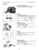
1.
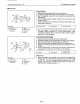
Disconnect the connector
(2)
from the alternator.
2.
Connect the leads
with
the terminals
as
shown in
the
figures.
3.
Start the engine and switch on all electrical loads
(such
as
head lights).
4.
Set
the engine
speed
at
approx.
2250
rpm, and measure
the
output
current.
5.
If
the measurement
is
less
than the factory specification,
the
alternator
is
defective.
6.
Run
the
engine
at
idling
speed
(low
rpm)
to
see
if
the
ammeter
reads a negative
(-)
value
(discharge). Then
increase the engine rpm
to
make
sure
the ammeter reads a
positive (
+) value (charge).
Alternator No-load Voltage
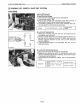
1.
Disconnect the connector
(2)
from the alternator.
2.
Connect
the
leads
with
the terminals
as
shown in
the
figures.
3.
Start the engine and set its
speed
approx. 2250 rpm.
4.
Disconnect the battery negative cord from
the
battery
(5).
5.
Measure the voltage
across
the alternator Bterminal and
the
chassis.
6.
If
the measurement
is
less
than
the
factory
specification,
disassemble the alternator and check the
IC
regulator.
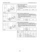
B022F045
(1)
Alternator
(2)
Alternator
2P
Connector
IG
(RY)
(3)
Bulb
(4)
Main
Switch
(5)
Battery
(6) Load
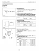
Output
current
Voltage
Factory spec.
Factory spec.
More
than
40 A
14.2
to
14.8 V
(at
25°C, 77°F)
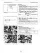
B022F044
(1)
Alternator
(2)
Alternator
2P
Connector
(3) Bulb
(4)
Main
Switch
(5)
Battery
(6) Load
(Reference)
.. Once the engine
has
started,
the
alternator
temperature
rises
quickly up
to
an
ambient temperature
of
70
to
90°C
(158
to
194
OF).
As
the
temperature
goes
higher
than
50°C
(122°F),
the alternator voltage slowly drops;
at
higher than
100°C
(212°F),
it
drops by about 1
V.
9-S15