
Installation Instructions


B1700·B2100·B2400 WSM,11771
8
HYDRAU
L1C
SYSTEM
(;]
HYDRAULIC SYSTEM
SERVICING
I
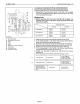
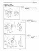
Distance:
"B"
I
~actory
spec.
I 19 mm
'---
..
0_.7_5_1n_.
_
8mm
0.31
in.
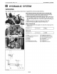
(9)
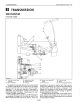
Bi-speed Turn Lever Grip
(10) Mid-PTO Gear ShiftLever Grip
(11)
Rear-PTO
Gear Shift Lever Grip
(12) Hi-Lo Gear Shift Lever Grip
(13) LeverGuide
(14) Bi-speed Turn Cable
(15) Cable Support
(16) Bi-speed Turn Lever
Rod
Factory
spec.
(1) Seat
(2) Lowering Speed Adjusting Knob
(3)
Seat Under Cover
(4)
Seat
Rail
(5)
Tool
Box
(6) Seat Stay
(7) Position Control Lever Grip
(8) Front Wheel Drive Lever Grip
(Reference)
I
Distance:"
A"
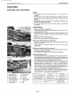
Seat, Seat Rail, Seat Stay and Seat Under Cover on page
8-S9
is
altered
as
explained below.
Seat, Seat Rail, Seat Stay, Seat Under Cover and Fender
(RH)
1.
Remove
the
seat
(1)
and lowering speed adjusting
knob
(2).
2.
Remove
the
tool
box
(5)
and seat under cover (3).
3.
Remove
the
position control lever
grip
(7),
front
wheel drive
lever
grip
(8), bi-speed
turn
lever
grip
(9), mid and rear-PTO
gear
shift
lever grips (10) (11) and Hi-Lo gear
shift
lever
grip
(12).
4.
Remove
the
left
and
right
hand side lever guide (13).
5.
Remove
the
seat stay
(6)
and seat rail
(4)
as
a unit.
(When reassembling)
• When connecting the bi-speed
turn
cable (14), make sure
the
distance
"A".
B177F410
D8-S1