
Installation Instructions


B1700·B21 00'B2400 WSM, 11770
6
FRONT
AXLE
B177P190
B177P189
Collar
Lock
Nut
Differential Yoke Shaft
RH
Differential Yoke Shaft
LH
Ball Bearing
Collar
(7)
(8)
(9)
(10)
(11
)
(12)
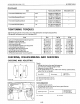
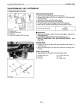
Spiral Bevel Pinion Shaft and Differential Gear Assembly
1.
Take
out
the differential yoke shaft
(9),
(10).
2.
Remove
the internal snap ring
(5).
3.
Tap
out
the spiral bevel pinion shaft
(3)
by
the
brass
rod and
hammer.
4.
Take
out
the differential gear assembly
(2),
ball bearing (11)
and collar
(12)
from
right
side
of
front
axle
case
(1).
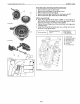
5.
Remove
the stake
of
lock
nut
(8),
and then remove
the
lock
nut
(8).
6.
Remove
the taper roller bearings
(6).
(When reassembling)
•
Replace
the lock
nut
(8)
with
new
ones.
• Apply grease
to
the
a-ring
of
front
axle
case
bosses.
• Install the
shims
and collars
tp
their
original position.
• Apply gear oil
to
the taper roller bearings (6) and install
them correctly, noting
their
direction.
• Stake the lock
nut
(8)
firmly.
(1)
FrontAxle
Case
(2)
Differential Gear Assembly
(3)
Spiral Bevel Pinion Shaft
(4) Adjusting Collar
(5) Internal
Snap
Ring
(6) Taper Roller Bearings
B177F606
B177F607
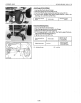
(1)
Collar
(8)
External Snap
Ring
(2)
Differential
Case
(9)
Screws
(3)
Thrust Collar
(10)
Pinion Shaft
(4)
Differential
Pinion
(11
)
Shim
(5)
Differential
Case
(12)
Differential
Side
Cover Gear
(6)
Ball Bearing
(13)
Straight
Pin
(7)
Spiral Bevel Gear
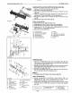
Differential Gear
1.
Remove
the differential
case
cover mounting screws
(9)
and
then take
out
the differential
case
cover (5), ball bearing
(6)
and spiral bevel gear
(7)
as
a unit.
2.
Remove
the external snap ring (8), and then remove
the
ball
bearing
(G)
and spiral bevel gear
(7)
as
a
unit
with
a puller.
3.
Remove
the straight pin
(13).
4.
Pull
out
the pinion shaft
(10)
and take
out
the
differential
pinions
(4)
and differential side gears (12).
II
NOTE
• Arrange the parts
to
know
their
original position.
(When reassembling)
•
Apply
molybdenum
disulfide
(Three
Bond
1901
or
equivalent)
to
the
inner
circumferential
surface
of
the
differential side gears
(12)
and differential pinions
(4).
• Install the pinion shaft
(10)
so
that
the hole on
it
may align
with
the hole on differential
case
(2),
and install the straight
pin (13).
Differential
case
cover
29.4
to
34.3
N'm
Tightening
torque
mounting screw
3.0
to
3.5
kgf'm
21.7
to
25.3
ft-Ibs
6-59