
Installation Instructions
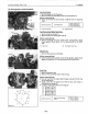
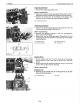

1
ENGINE
B1700'B21 00'B2400 WSM, 11770
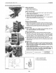
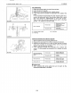
(1)
Main
Bearing
Case
Assy.
(2)
Main
Bearing
Case
2
(with
mark
U B
U
)
(3)
Main
Bearing
Case
1
(with
mark
U
AU)
(4)
Aligning
Mark
Main Bearing
Case
1.
Remove bearing
case
bolt
1, and
the
main bearing
case
(1),
(2),
(3)
from
the crankshaft.
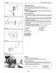
II
IMPORTANT
• Properly arrange the main bearing
cases
and
the
bearings
for
their
right
combinations.
(When reassembling)
• Apply engi
ne
oi I
to
the
beari ngs and
fit
the
case.
• Fit the main bearing
case
with
the
FLYWHEEL
mark set on
the side
of
the flywheel.
• Fit the main bearing
case
wheel
with
the
bolt
holes set on
the
side
of
the flywheel and
the
side metals
with
the
oil
groove facing outside.
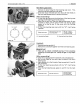
29.4to34.3
N'm
Tightening
torque
Bearing
case
bolt
1
3.0
to
3.5
kgf'm
21.7
to
25.3 ft-Ibs
/'
1
2
0343F130
0343F131
SERVICING
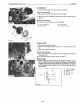
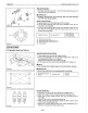
(1) Cylinder Head and Valves
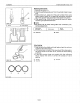
Cylinder Head Surface Flatness
1.
Thoroughly clean the cylinder head surface.
2.
Place
a straightedge on the cylinder head's
four
sides and
two
diagonal
as
shown in the figure.
Measure
the
clearance
with
a feeler gauge.
3.
If
the measurement exceeds
the
allowable
limit,
replace it.
II
NOTE
• Do
not
place
the
straight
edge on the combustion chamber.
II
IMPORTANT
•
Be
sure
to
check the valve recessing
after
correcting.
0087F053
Cylinder head surface
flatness
Allowable
limit
0.05
mm
0.0019 in.
0087F054
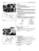
--=-
'---
~
r!lJG::IIV
[lJ1lW
RC-AA
RC-AB
Rp.:A
C
~
~
~
~
(1)
(2)
(3)
ST10F042
Cylinder Head Flaw
1.
Prepare
an
air
spray red check (Code No: 07909-31371).
2.
Clean the surface
of
the cylinder head
with
detergent
(1).
3.
Spray the cylinder head surface
with
the
red
permeative
liquid (2).
Leave
it
five
to
ten minutes
after
spraying.
4.
Wash away the red permeative liquid on
the
cylinder head
surface
with
the detergent (1).
5.
Spray the cylinder head surface
with
white
developer (3).
If
flawed,
it
can
be
identified
as
red marks.
1-530