
Installation Instructions


5
BRAKES
[2] OPERATION
B177F502
B1700·B2100·B2400 WSM,11770
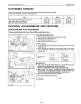
(4) Rear Axle
Case
(5) Steel Ball
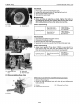
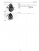
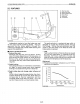
III During Braking
When
the
brake pedal
is
pressed,
the
linkage
causes
the
brake
cam
lever (8) and brake cam (7)
to
turn
into
the
direction
of
arrow
shown in
the
above
figure.
Therefore,
the
cam
plate
(1)
also moves
the
direction
of
arrow.
At
this
time,
since
the
cam plate
(1) rides on
the
steel balls
(5)
set in
the
grooves
of
the
rear
axle
case
to
press
the
brake
disc (3),
the
differential
gear shaft (6)
is
braked by
the
frictional
force generated by
the
cam
plate (1) and brake disc
(3).
(1)
Cam
Plate
(2) Friction Plate
(3) Brake
Disc
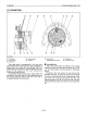
The brake
body
is
incorporated
in
the
rear axle
case
(4)
filled
with
transmission oil and
is
designed
to
brake
when
the
brake
disc (3) spl ined
with
the
differential
gear
shaft
(6)
is
pressed against
the
cam
plate
(1)
by
means
of
the
cam
mechanism
incorporating
steel balls (5).
For
greater
braking
force,
four
brake
discs are
provided
at
the
right
and
left
sides respectively, and
the
friction
plate (2) fixed
to
the
rear axle
case
is
arranged
between
the
brake
discs.
(6) Brake Shaft
(Differential Gear Shaft)
(7) Brake
Cam
(8) Brake
Cam
Lever
5-M2