
Installation Instructions


3
TRANSMISSION
~
TRANSMISSION
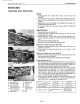
MECHANISM
(1) Control Linkage
B193F301
B1700·B2100·B2400 WSM,11772
o
10
(1) Trunnion Control Lever
Assembly
(2) Neutral Adjuster
(3) Speed Control
Rod
(4) Speed Set Lever
(5) Damper
(6) Speed Control Pedal
(HST
Pedal)
(7) Trunnion
Arm
(8)
Trunnion Lever
(9) Roller
(10)
HST
Pedal Spring Assembly
The speed control pedal
(6)
and
the
trunnion
shaft
of
variable swashplate are
linked
with
the
speed
control
rod
(3)
and
the
trunnion
control
lever
assembly (1).
As
the
front
footrest
of
the
pedal
is
depressed,
the
swashplate
rotates
and
forward
travelling
speed increases. Depressing
the
rear
footrest increases reverse speed.
The
roller
(9)
on
the
trunnion
lever
(8)
holded
with
spring seats
the
detent
of
the
trunnion
arm (7)
so
that
the
trunnion
lever returns
to
neutral. Then,
the
swashplate
is
returned
to
neutral
with
the
trunnion
control lever assembly, by means
of
HST
pedal spring
assembly
(10),
when
the
pedal
is
released. The
damper
(5)
connected
to
the
speed
control
pedal
restricts
the
movement
of
the
linkage
to
prevent
abrupt
operation
or
reversing.
The speed set lever
(4)
linked
to
the
speed control
pedal enables the linkage
not
to
return
to
neutral
and
to
keep a certain forward speed
while
the
speed
control pedal
is
released.
E3-M1