ABBREVIATION LIST Abbreviations Definitions 2WD Two Wheel Drive 4WD Four Wheel Drive API American Petroleum Institute ASABE American Society of Agricultural and Biological Engineers, USA ASTM American Society of Testing and Materials, USA DIN Deutsches Institut fur Normung, GERMANY DT Dual Traction [4WD] fpm Feet Per Minute GST Glide Shift Transmission Hi-Lo High Speed-Low Speed HST Hydrostatic Transmission m/s Meters Per Second PTO Power Take Off RH/LH Right-hand and left-hand
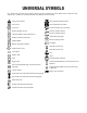
UNIVERSAL SYMBOLS As a guide to the operation of your tractor, various universal symbols have been utilized on the instruments and controls. The symbols are shown below with an indication of their meaning.
FOREWORD You are now the proud owner of a KUBOTA Tractor. This tractor is a product of KUBOTA quality engineering and manufacturing. It is made of fine materials and under a rigid quality control system. It will give you long, satisfactory service. To obtain the best use of your tractor, please read this manual carefully. It will help you become familiar with the operation of the tractor and contains many helpful hints about tractor maintenance.
CONTENTS SAFE OPERATION ................................................................................................. 1 SERVICING OF TRACTOR......................................................................................... 1 SPECIFICATIONS....................................................................................................... 2 SPECIFICATION TABLE ......................................................................................... 2 TRAVELING SPEEDS ...........................
CONTENTS Easy Checker (TM)......................................................................................................... 25 Fuel Gauge .....................................................................................................................26 Coolant Temperature Gauge .......................................................................................... 26 Hourmeter / Tachometer.................................................................................................
CONTENTS MAINTENANCE......................................................................................................... 46 SERVICE INTERVALS .......................................................................................... 46 LUBRICANTS, FUEL AND COOLANT .................................................................. 47 PERIODIC SERVICE................................................................................................. 49 HOW TO OPEN THE HOOD .................................
CONTENTS Replacing Air Cleaner Primary Element and Secondary Element.................................. 66 EVERY 2 YEARS................................................................................................... 67 Flushing Cooling System and Changing Coolant ........................................................... 67 Anti-Freeze ..................................................................................................................... 67 Replacing Radiator Hose (Water pipes) ..........
SAFE OPERATION 1 SAFE OPERATION Careful operation is your best insurance against an accident. Read and understand this manual carefully before operating the tractor. All operators, no matter how much experience they may have, should read this and other related manuals before operating the tractor or any implement attached to it. It is the owner's obligation to instruct all operators in safe operation. 1. BEFORE OPERATING THE TRACTOR 1. Know your equipment and its limitations.
2 SAFE OPERATION 13. Use proper weights on the front or rear of the tractor to reduce the risk of upsets. When using the front loader, put an implement or ballast on the 3-point hitch to improve stability. Follow the safe operating procedures specified in the implement or attachment manual. 14. The narrower the tread, the greater the risk of a tractor upset. For maximum stability, adjust the wheels to the widest practical tread width for your application. (See "TIRES, WHEELS AND BALLAST" section.
SAFE OPERATION 8. When parking your machine if at all possible park on a firm, flat and level surface; if not, park across a slope. Set the parking brake(s), lower the implements to the ground, remove the key from the ignition and lock the cab door (if equipped) and chock the wheels. C Operating on slopes Slopes are major factor related to loss-of-control and tipover accidents, which can result in severe injury or death. All slopes require extra caution. 1. To avoid upsets, always back up steep slopes.
4 SAFE OPERATION 3. PARKING THE TRACTOR 1. Disengage the PTO, lower all implements to the ground, place all control levers in their neutral positions, set the parking brake, stop the engine, and remove the key. 2. Make sure that the tractor has come to a complete stop before dismounting. 3. Avoid parking on steep slopes, if possible park on flat ground, if not, park across a slope, always with attachment on the ground. 5. USING 3-POINT HITCH 1.
SAFE OPERATION 7. Disconnect the battery's ground cable before working on or near electric components. 8. To avoid the possibility of battery explosion, do not use or charge the refillable type battery if the fluid level is below the LOWER ( lower limit level ) mark. Check the fluid level regularly and add distilled water as required so that the fluid level is between the UPPER and LOWER levels. 9.
6 SAFE OPERATION 7.
SAFE OPERATION 7
8 SAFE OPERATION 8. CARE OF DANGER, WARNING AND CAUTION LABELS 1. 2. 3. 4. Keep danger, warning and caution labels clean and free from obstructing material. Clean danger, warning and caution labels with soap and water, dry with a soft cloth. Replace damaged or missing danger, warning and caution labels with new labels from your local KUBOTA Dealer.
SERVICING OF TRACTOR SERVICING OF TRACTOR Your dealer is interested in your new tractor and has the desire to help you get the most value from it. After reading this manual thoroughly, you will find that you can do some of the regular maintenance yourself. However, when in need of parts or major service, be sure to see your KUBOTA Dealer. For service, contact the KUBOTA Dealership from which you purchased your tractor or your local KUBOTA Dealer.
2 SPECIFICATIONS SPECIFICATIONS SPECIFICATION TABLE Model PTO power* B2320DTN-1 B2320DT B2320HSDN B2320HSD kW (HP) 13.4 (18.0) 12.7 (17.0) Maker D1005-E3-D22 Type 14.2 (19.0) 15.7 (21.0) D1105-E3-D22 D1305-E3-D22 E-TVCS, liquid cooled, 3-cylinder diesel Number of cylinders Bore and stroke Total displacement Engine gross power* 3 76 x 73.6 (3.0 x 2.9) 78 x 78.4 (3.1 x 3.1) 78 x 88 (3.1 x 3.5) cm (cu.in.) 1001 (61.1) 1123 (68.5) 1261 (77.0) kW (HP) 17.2 (23.0) 19.4 (26.0) 21.6 (29.
SPECIFICATIONS Model Tires B2320DTN-1 B2320DT B2320HSDN B2320HSD 5-12 6-12 5-12 6-12 7-12 Rear 8-16 9.5-16 8-16 9.5-16 11.2-16 Integral type power steering Gear shift, 9 forward and 3 reverse Transmission Brake m (feet) Pump capacity 2.1 (6.9) Position control valve Hydraulic control system L / min (gals / min) Position control valve Quarter inching valve 3P: 17.9 (4.7), Power steering: 13.5 (3.6) SAE Category 1 At lift points kg (lbs.
4 SPECIFICATIONS TRAVELING SPEEDS [HST Type] (At rated engine rpm) Model B2320HSDN Tire size (Rear) 8 - 16 Farm B2320 9.5 - 16 Farm 33 x 12.5 - 15 Turf Range gear shift lever km / h mph km / h mph km / h mph Low 0 to 5.2 0 to 3.2 0 to 5.6 0 to 3.5 0 to 5.6 0 to 3.5 Middle 0 to 8.7 0 to 5.4 0 to 9.3 0 to 5.8 0 to 9.3 0 to 5.8 High 0 to 17.7 0 to 11.0 0 to 18.9 0 to 11.7 0 to 18.9 0 to 11.7 Low 0 to 4.2 0 to 2.6 0 to 4.5 0 to 2.8 0 to 4.5 0 to 2.8 Middle 0 to 7.
IMPLEMENT LIMITATIONS 5 IMPLEMENT LIMITATIONS The KUBOTA Tractor has been thoroughly tested for proper performance with implements sold or approved by KUBOTA. Use with implements which are not sold or approved by KUBOTA and which exceed the maximum specifications listed below, or which are otherwise unfit for use with the KUBOTA Tractor may result in malfunctions or failures of the tractor, damage to other property and injury to the operator or others.
6 IMPLEMENT LIMITATIONS Implement B2320DTN B2320HSDN B2320 Max. cutting width Max. weight cm (in.) kg (lbs.) Rotary-cutter Max. cutting width (1 Blade) Max. weight cm (in.) kg (lbs.) 122 (48) 204 (450) Rear-mount Max. cutting width (2 or 3 Blade) Max. weight cm (in.) kg (lbs.) 152 (60) 227 (500) Mid-mount Mower Remarks B2620 B2920 152 (60) 140 (300) - Flail-mower Max. cutting width cm (in.) 107 (42) 122 (48) Sickle bar Max. cutting width cm (in.) 122 (48) 152 (60) cm (in.
INSTRUMENT PANEL AND CONTROLS 7 INSTRUMENT PANEL AND CONTROLS B Instrument Panel, Switches and Hand Controls ILLUSTRATED CONTENTS (1) Turn signal / Hazard light indicator ....................... (2) Coolant temperature gauge ................................. (3) Turn signal light switch ......................................... (4) Head light switch .................................................. (5) Hourmeter / Tachometer ...................................... (6) Easy Checker (TM) ..................
8 INSTRUMENT PANEL AND CONTROLS B Foot and Hand Controls [HST Type] ILLUSTRATED CONTENTS (1) Clutch pedal ................................................... (2) Speed set lever .............................................. (3) Speed control pedal ....................................... (4) 3-Point hitch lowering speed knob .................. (5) Cutting height control dial (if equipped) .......... (6) Differential lock pedal ..................................... (7) Range gear shift lever .............
INSTRUMENT PANEL AND CONTROLS 9 B Foot and Hand Controls [Manual Transmission Type] ILLUSTRATED CONTENTS (1) Clutch pedal .................................................... 21 (2) Differential lock pedal ...................................... 27 (3) 3-Point hitch lowering speed knob ................... 35 (4) Cutting height control dial (if equipped) ............ --(5) Range gear shift lever ...................................... 22 (6) PTO gear shift lever .........................................
10 INSTRUMENT PANEL AND CONTROLS B Pedal Location Label The label is located on the cover under seat.
PRE-OPERATION CHECK PRE-OPERATION CHECK DAILY CHECK To prevent trouble from occurring, it is important to know the condition of the tractor well. Check it before starting. To avoid personal injury: A Be sure to check and service the tractor on a level surface with the engine shut off and the parking brake "ON" and implement lowered to the ground.
12 OPERATING THE ENGINE OPERATING THE ENGINE To avoid personal injury: A Read "Safe Operation" in the front of this manual. A Read the danger, warning and caution labels located on the tractor. A To avoid the danger of exhaust fume poisoning, do not operate the engine in a closed building without proper ventilation. A Never start engine while standing on ground. Start engine only from operator's seat.
OPERATING THE ENGINE 3. [HST Type] Place the speed set lever in "OFF" position. Place the speed control pedal in "NEUTRAL" position. Place the range gear shift lever (L-M-H) in "NEUTRAL" position. 4. Lock the loader control lever in "NEUTRAL" position. (if equipped) (1) Loader control lever (2) Lock lever (1) Range gear shift lever (L-M-H) (2) Speed set lever (3) Speed control pedal (A) "OFF" (B) "ON" (H) "HIGH" (M) "MIDDLE" (L) "LOW" (N) "NEUTRAL POSITION" (A) "LOCK" 5.
14 OPERATING THE ENGINE [B2320DTN, B2320HSDN] Place the position control lever in "LOWEST" position. 7. Insert the key into the key switch and turn it "ON". (A) "OFF" (B) "ON" (1) Position control lever (A) "DOWN" 6. Set the throttle lever to about 1/2 way. (1) Hand throttle lever (C) "PREHEAT" (D) "START" (A) "INCREASE" (B) "DECREASE" C Check Easy Checker(TM) lamps: 1. When the key is turned "ON", lamps (3) (4) should come on.
OPERATING THE ENGINE 8. Fully depress the clutch pedal, turn the key to "PREHEAT" position and hold it for about 2 to 3 seconds. Temperature Preheating Time Over 0 C (32 F) 2 to 3 sec. 0 to -5 C (32 to 23 F) 5 sec. -5 to -15 C (23 to 5 F) 10 sec. A Glow plug indicator (5) comes on while engine is being preheated. 9. Turn the key to "START" position and release when the engine starts.
16 OPERATING THE ENGINE JUMP STARTING To avoid personal injury: A Battery gases can explode. Keep cigarettes, sparks, and flames away from battery. A If tractor battery is frozen, do not jump start engine. A Do not connect other end of negative (-) jumper cable to negative (-) terminal of tractor battery. When jump starting engine, follow the instructions below to safely start the engine. 1. Bring helper vehicle with a battery of the same voltage as disabled tractor within easy cable reach.
OPERATING THE TRACTOR 17 OPERATING THE TRACTOR OPERATING NEW TRACTOR How a new tractor is handled and maintained determines the life of the tractor. A new tractor just off the factory production line has been, of course, tested, but the various parts are not accustomed to each other, so care should be taken to operate the tractor for the first 50 hours at a slower speed and avoid excessive work or operation until the various parts become "broken-in.
18 OPERATING THE TRACTOR 2. Fold the ROPS. BTo Raise the ROPS to Upright Position 1. Remove both hair pins and set pins. To avoid personal injury: A Hold the ROPS tightly with both hands and fold the ROPS slowly and carefully. (1) Set pin (2) Hair pin 2. Raise ROPS to the upright position. (1) ROPS 3. Insert both set pins and secure them with the hair pins. To avoid personal injury: A Make sure that both set pins are properly installed and secured with the hair pins.
OPERATING THE TRACTOR BAdjustment of Foldable ROPS A Adjust free fall of the ROPS upper frame regularly. A If you feel less friction in folding the ROPS, tighten the nut (1) until you feel the right friction in the movement. 19 STARTING 1. Adjusting the operator's position. BOperator's Seat To avoid personal injury: A Make sure that the seat is completely secured after each adjustment. A Do not allow any person other than the driver to ride on the tractor.
20 OPERATING THE TRACTOR BSeat Belt To avoid personal injury: A Always use the seat belt when the ROPS is installed. A Do not use the seat belt if a foldable ROPS is down or there is no ROPS. Adjust the seat belt for proper fit and connect to the buckle. The seat belt is auto-locking retractable type. 2. To indicate a left turn without hazard lights, turn the turn signal switch counterclockwise. 3.
OPERATING THE TRACTOR 3. Checking the brake pedal. 21 4. Raise the implement. (See "HYDRAULIC UNIT" section.) BBrake Pedals (Right and Left) To avoid personal injury: A Applying only one rear wheel brake at high speeds could cause the tractor to swerve or roll-over. To avoid personal injury: A An accident may occur if the tractor is suddenly braked, such as by heavy towed loads shifting forward or loss of control. A The braking characteristics are different between two and four wheel drive.
22 OPERATING THE TRACTOR A Avoid operating the tractor with your foot resting on the clutch pedal. A Select proper gear and engine speed depending on the type of job. 6. Selecting the Travel Speed. BRange Gear Shift Lever (L-M-H) [HST Type] BMain Gear Shift Lever & Range Gear Shift Lever (L-M-H) [Manual Transmission Type] The main gear shift lever pattern is in the form of an "H". The range gear shift lever moves in the form of an "I" in 3 stages, "HIGH", "MIDDLE" and "LOW".
OPERATING THE TRACTOR BFront Wheel Drive Lever 7. Accelerate the engine. To avoid personal injury: A Do not engage the front wheel drive when traveling at road speed. A When driving on icy, wet or loose surfaces, make sure the tractor is correctly ballasted to avoid skidding and loss of steering control. Operate at reduced speed and engage front wheel drive. A An accident may occur if the tractor is suddenly braked, such as by heavy towed loads shifting forward or loss of control.
24 OPERATING THE TRACTOR 8. Unlock the parking brake and slowly release the clutch. BParking Brake To release the parking brake, depress the brake pedals again. 9. Depress the speed control pedal. [HST Type] BSpeed Control Pedal To avoid personal injury: A Do not operate if tractor moves on level ground with foot off of Speed Control Pedal. A Consult your local KUBOTA Dealer. Forward Pedal Depress the forward pedal with the toe of your right foot to move forward.
OPERATING THE TRACTOR 25 STOPPING BSpeed Set Device The Speed Set Device is designed for tractor operating efficiency and operator comfort. This device will provide a constant forward operating speed by mechanically holding the speed control pedal at a selected position. C To engage Speed Set Device 1. Accelerate speed to desired level using Speed Control Pedal, and push the speed set lever down to the "ON" position. 2. Release Speed Control Pedal and desired speed will be maintained.
26 OPERATING THE TRACTOR Electrical charge If the alternator is not charging the battery, the warning lamp in the Easy Checker(TM) will come on. If this should happen during operation, check the electrical charging system or consult your local KUBOTA Dealer. A For checking and servicing of your tractor, consult your local KUBOTA Dealer for instructions. BFuel Gauge When the key switch is on, the fuel gauge indicates the fuel level. Be careful not to empty the fuel tank.
OPERATING THE TRACTOR PARKING OPERATING TECHNIQUES BParking Brake BDifferential Lock To avoid personal injury: A Always set the parking brake, stop the engine and remove the key before leaving the tractor seat. 1. When parking, be sure to set the parking brake. To set the parking brake; (1) Interlock the brake pedals. (2) Depress the brake pedals. (3) Latch the brake pedals with the parking brake lever.
28 OPERATING THE TRACTOR A When using the differential lock, always slow the engine down. A To prevent damage to power train, do not engage differential lock when one wheel is spinning and the other is completely stopped. A If the differential lock cannot be released in the above manner, step lightly on the brake pedals alternately. BOperating the Tractor on a Road To avoid personal injury: A To help assure straight line stops when driving at transport speeds, lock the brake pedals together.
PTO 29 PTO PTO OPERATION To avoid personal injury: A To prevent damage to PTO driven equipment and possibly causing personal injury, use the 2nd rear PTO speed and mid-PTO speed only when these higher rpms are specifically recommended by the implement manufacturer. A Replace restricting plate to (C) position after use of the 2nd PTO speed. A To avoid shock loads to the PTO, reduce engine speed when engaging the PTO, then open the throttle to the recommended speed.
30 PTO BPTO shaft Cover and Shaft Cap Keep the PTO shaft cover in place at all times. Replace the PTO shaft cap when the PTO is not in use. Before connecting or disconnecting a drive shaft to PTO shaft, be sure engine is "OFF" and raise up the PTO shaft cover. Afterward be sure to return the PTO shaft cover to the "NORMAL POSITION".
THREE-POINT HITCH & DRAWBAR THREE-POINT HITCH & DRAWBAR (1) Top link (2) Lifting rod (Left) (3) Check chains (4) Turnbuckle (5) Lower link (6) Drawbar (7) Lifting rod (Right) (8) Top link holder 31
32 THREE-POINT HITCH & DRAWBAR 3-POINT HITCH 2. Attaching and detaching implements 1. Make preparations for attaching implement. BSelecting the holes of lifting rods and lower links There are two holes in the lower links. For most operations the lifting rods should be attached to the (A) holes. To avoid personal injury: A Be sure to stop the engine and remove the key. A Do not stand between tractor and implement unless parking brake is applied.
THREE-POINT HITCH & DRAWBAR BCheck Chains Remove the snap pin and adjust the turnbuckle to control horizontal sway of the implement. After adjustment, re-set the snap pin. 33 DRAWBAR To avoid personal injury: A Never pull from the top link, the rear axle or any point above the drawbar. Doing so could cause the tractor to tip over rearward causing personal injury or death. BAdjusting Drawbar Length When towing an implement, use of (B) hole in drawbar is recommended.
34 HYDRAULIC UNIT HYDRAULIC UNIT 3-POINT HITCH CONTROL SYSTEM BHydraulic Control [Except B2320DTN, B2320HSDN] Operating the hydraulic control lever actuates the hydraulic lift arm, which controls the height of 3-point hitch mounted implement. To lower implement, push the lever forward; to raise it, pull the lever back. After setting the implement to the desired height, move the lever back to "NEUTRAL" position.
HYDRAULIC UNIT 35 AUXILIARY HYDRAULICS BImplement Lowering Limit [Except B2320DTN, B2320HSDN] The implement lowering limit can be changed by shifting the locker (A). Hydraulic outlet is provided on the tractor. (without loader valve only) BHydraulic Block Type Outlet Hydraulic block type outlet is useful when adding hydraulically operated equipment such as front end loader, front blade, etc. When implement is attached 1. Remove the block cover. 2. Attach the block outlet cover.
36 HYDRAULIC UNIT A The "tank" port flow from implement valve should be connected to the port located on the right hand side of transmission case. [Rear outlet] [B2320DTN, B2320HSDN] Two hydraulic outlets are provided on the tractor. (1) Return port (A) To implement inlet (1) Block cover Max. flow (2) Block outlet cover (option) 16.6 L/min (4.4 U.S. gals/min) (3) Outlet Max. pressure (4) Inlet 13.2 to 13.
HYDRAULIC UNIT DUAL REMOTE HYDRAULIC CONTROL SYSTEM (if equipped) The tractor is equipped with the double-acting 2-segment hydraulic control valve for front loader. To apply the hydraulic power take-off for general attachments, keep the following point in mind. BControl Lever and Hydraulic Hose Connections 37 A This control valve is provided with the Regeneration position.
38 HYDRAULIC UNIT BValve Lock To avoid injury from crushing: A Do not utilize the valve lock for machine maintenance or repair. A The valve lock is to prevent accidental actuation when implement is not in use or during transport. The control valve is equipped with a valve lock feature. The control valve is locked in "NEUTRAL" position. The lock is not intended and will not prevent a leak down of the implement during the period of storage.
HYDRAULIC UNIT 39 BHydraulic Control Unit Use Reference Chart In order to handle the hydraulics properly, the operator must be familiar with the following. Though this information may not be applicable to types of implements and soil conditions, it is useful for general conditions.
40 TIRES, WHEELS AND BALLAST TIRES, WHEELS AND BALLAST TIRES WHEEL ADJUSTMENT To avoid personal injury: A Do not attempt to mount a tire on a rim. This should be done by a qualified person with the proper equipment. A Always maintain the correct tire pressure. Do not inflate tires above the recommended pressure shown in the operator's manual. A Do not use tires other than those approved by KUBOTA.
TIRES, WHEELS AND BALLAST C Except USA models C USA models Tire Models 5 - 12 Farm B2320 HSDN B2320 DTN 6 - 12 Farm B2320 HSDN B2320 DTN B2320 7 - 12 Farm B2620 B2920 23x8.50 - 12 Turf B2320 B2620 B2920 21x8.00 - 10 Bar B2320 B2620 B2920 23x8.50 - 12 Ind. B2320 B2620 B2920 Tread Tire Models 6 - 12 Farm B2320 7 - 12 Farm B2620 B2920 22x8.50 - 12 Turf B2320 24x8.
42 TIRES, WHEELS AND BALLAST BRear Wheels [B2320DTN, B2320HSDN] Rear tread width can be adjusted as shown. To change the tread width 1. Loosen the nut of cotter pin bolt. 2. Remove the snap pin and wheel hub pin. 3. Change the tread to the desired position. 4. Re-set the wheel hub pin, snap pin and cotter pin bolt. C USA models Tire Models 8 - 16 Farm B2320 HSDN B2320 DTN 8.3 - 16 Farm B2320 HSDN B2320 DTN Tread A Always attach tires as shown in the drawings.
TIRES, WHEELS AND BALLAST [Except B2320DTN, B2320HSDN] Rear tread width can not be adjusted. C Except USA models Tire Models 9.5 - 16 Farm B2320 9.5 - 18 Farm B2620 B2920 31x 13.5 15 Turf B2320 315/75D - 15 Turf B2620 B2920 C USA models Tire Models 9.5 - 16 Farm B2320 11.2 - 16 Farm B2620 B2920 33x 12.5 - 15 Turf B2320 B2620 B2920 31x 15.5 - 15 Bar B2320 B2620 B2920 12 - 16.5 Ind.
44 TIRES, WHEELS AND BALLAST A Always attach tires as shown in the drawings. A If not attached as illustrated, transmission parts may be damaged. BALLAST To avoid personal injury: A Additional ballast will be needed for transporting heavy implements. When the implement is raised, drive slowly over rough ground, regardless of how much ballast is used. A Do not fill the front wheels with liquid. BFront Ballast Add weights if needed for stability and improving traction.
TIRES, WHEELS AND BALLAST BRear Ballast Add weight to rear wheels if needed to improve traction or for stability. The amount of rear ballast should be matched to job and the ballast should be removed when it is not needed. The weight should be added to the tractor in the form of liquid ballast. C Liquid Ballast in Rear Tires Water and calcium chloride solution provides safe economical ballast. Used properly, it will not damage tires, tubes or rims.
46 MAINTENANCE MAINTENANCE SERVICE INTERVALS No. Indication on hour meter Items 50 100 150 200 250 300 350 400 450 500 550 600 650 700 Since then Ref.
MAINTENANCE 47 A The jobs indicated by must be done after the first 50 hours of operation. *1 Air cleaner should be cleaned more often in server dusty conditions. *2 Every year or after 6 cleanings. *3 Replace only if necessary. *4 Consult your local KUBOTA Dealer for this service. *5 When the battery is used for less than 100 hours per year, check the fluid level annually. A The items listed above (@ marked) are registered as emission related critical parts by KUBOTA in the U.S.
48 MAINTENANCE C Engine Oil: A Oil used in the engine should have an American Petroleum Institute (API) service classification and Proper SAE Engine Oil according to the ambient temperatures as shown above: A With the emission control now in effect, the CF-4 and CG-4 lubricating oils have been developed for use of a lowsulfur fuel on on-road vehicle engines.
PERIODIC SERVICE 49 PERIODIC SERVICE To avoid personal injury: A Do not work under any hydraulically supported devices. They can settle, suddenly leak down, or be accidentally lowered. If necessary to work under tractor or any machine elements for servicing or adjustment, securely support them with stands or suitable blocking beforehand. A To close the hood, hold the hood and release the support rod.
50 PERIODIC SERVICE DAILY CHECK BEngine Side Cover 1. Tilt down the front grille forward. 2. Lift up the front of the engine side cover and free the upper and lower projections. For your own safety and maximum service life of the machine, make a thorough daily inspection before operating the machine to start the engine. To avoid personal injury: A Be sure to check and service the tractor on a level surface with the engine shut off and the parking brake "ON" and implement lowered to the ground.
PERIODIC SERVICE BChecking and Refueling To avoid personal injury: A Do not smoke while refueling. A Be sure to stop the engine before refueling. 1. Turn the key switch to "ON", check the amount of fuel by fuel gauge. 2. Fill fuel tank when fuel gauge shows 1/4 or less fuel in tank. 51 BChecking Engine Oil Level To avoid personal injury: A Be sure to stop the engine before checking the oil level. 1. Park the machine on a flat surface. 2.
52 PERIODIC SERVICE BChecking Transmission Fluid Level 1. Park the machine on a flat surface, lower the implement and shut off engine. 2. To check the oil level, draw out the dipstick, wipe it clean, replace it, and draw it out again. Check to see that the oil level lies between the two notches. If the level is too low, add new oil to the prescribed level at the oil inlet. (See "LUBRICANTS" in "MAINTENANCE" section.
PERIODIC SERVICE BCleaning Grill and Radiator Screen To avoid personal injury: A Be sure to stop the engine and remove the key before removing the screen. 1. Check front grill and side screens to be sure they are clean of debris. 2. Detach the screen and remove all foreign materials and clean the front of radiator completely. 53 BChecking Brake Pedals and Clutch Pedal 1. Inspect the brake and clutch pedals for free travel, and smooth operation. 2.
54 PERIODIC SERVICE BChecking and Cleaning of Electrical Wiring and Battery Cables To avoid personal injury: A A loosened terminal or connector, or damaged wire may affect the performance of electrical components or cause short circuits. Leakage of electricity could result in a fire hazard, a dead battery or damage to electrical components. A Replace damaged wires or connections promptly. A If a fuse blows soon after replacement, DO NOT USE A LARGER THAN RECOMMENDED FUSE OR BYPASS THE FUSE SYSTEM.
PERIODIC SERVICE 55 7. If it does not stop, consult your local KUBOTA Dealer for this service. A If the engine cranks during any of these tests, consult your local KUBOTA Dealer to have unit checked before operating. (1) Battery terminals BChecking Engine Start System To avoid personal injury: A Do not allow anyone near the tractor while testing. A If the tractor does not pass the test do not operate the tractor. [Manual Transmission Type] C Preparation before testing. 1. Sit on operator's seat. 2.
56 PERIODIC SERVICE [HST Type] C Preparation before testing. 1. Sit on operator's seat. 2. Set the parking brake and stop the engine. 3. Shift the range gear shift lever to "NEUTRAL" position. Place the speed control pedal in "NEUTRAL" position. 4. Shift the PTO gear shift lever to "NEUTRAL" position. 5. Fully depress the clutch pedal. C 1. 2. 3. 4. Test : Switch for the speed control pedal. Fully depress the clutch pedal. Depress the speed control pedal. Turn the key to "START" position.
PERIODIC SERVICE 57 EVERY 100 HOURS BBattery To avoid the possibility of battery explosion: For the refillable type battery, follow the instructions below. A Do not use or charge the refillable type battery if the fluid level is below the LOWER (lower limit level) mark. Otherwise, the battery component parts may prematurely deteriorate, which may shorten the battery's service life or cause an explosion.
58 PERIODIC SERVICE BCleaning Air Cleaner Primary Element (1) Battery 1. To slow charge the battery, connect the battery positive terminal to the charger positive terminal and the negative to the negative, then recharge in the standard fashion. 2. A boost charge is only for emergencies. It will partially charge the battery at a high rate and in a short time. When using a boost-charged battery, it is necessary to recharge the battery as early as possible.
PERIODIC SERVICE BCleaning Fuel Filter This job should not be done in the field, but in a clean place. 1. Loosen and remove the filter bowl, and rinse the inside with kerosene. 2. Take out the element and dip it in the kerosene to rinse. 3. After cleaning, reassemble the fuel filter, keeping out dust and dirt. 4. Bleed the fuel system. (See "SERVICE AS REQUIRED" in "PERIODIC SERVICE" section.
60 PERIODIC SERVICE BAdjusting Clutch Pedal Proper clutch pedal free travel 20 to 30 mm (0.8 to 1.2 in.) on the pedal 1. Stop the engine and remove the key. 2. Slightly depress the clutch pedal and measure free travel at top of pedal stroke. 3. If adjustment is needed, loosen the lock nut and turn the turnbuckle to adjust the rod length within acceptable limits. 4. Retighten the lock nut.
PERIODIC SERVICE BChecking Fuel Line 1. Check to see that all lines and hose clamps are tight and not damaged. 2. If hoses and clamps are found worn or damaged, replace or repair them at once. (1) Fuel lines (2) Clamp bands 61 EVERY 200 HOURS BReplacing Engine Oil Filter To avoid personal injury: A Be sure to stop the engine before changing the oil filter cartridge. A Allow engine to cool down sufficiently, oil can be hot and can burn. 1. Remove the oil filter. 2.
62 PERIODIC SERVICE BChanging Engine Oil To avoid personal injury: A Be sure to stop the engine and remove the key before changing the oil. A Allow engine to cool down sufficiently, oil can be hot and can burn. 1. To drain the used oil, remove the drain plug at the bottom of the engine and drain the oil completely into the oil pan. All the used oil can be drained out easily when the engine is still warm. 2. After draining reinstall the drain plug. 3.
PERIODIC SERVICE BReplacing Transmission Oil Filter [HST Type] To avoid personal injury: A Be sure to stop the engine before changing the oil filter cartridge. A Allow engine to cool down sufficiently, oil can be hot and can burn. 63 4. Put a film of clean transmission oil on the rubber seal of the new filter. 5. Quickly tighten the filter until it contacts the mounting surface, then, with a filter wrench, tighten it an additional 1 turn only. 6.
64 PERIODIC SERVICE BChecking Radiator Hose and Clamp BChecking Intake Air Line Check to see if radiator hoses are properly fixed every 200 hours of operation or six months, whichever comes first. 1. If hose clamps are loose or water leaks, tighten bands securely. 2. Replace hoses and tighten hose clamps securely, if radiator hoses are swollen, hardened or cracked. Replace hoses and hose clamps every 2 years or earlier if checked and found that hoses are swollen, hardened or cracked. 1.
PERIODIC SERVICE BChanging Transmission Fluid / Replacing Hydraulic Oil Filter 65 3. Remove the oil filter. To avoid personal injury: A Be sure to stop the engine before changing the oil filter cartridge. A Allow engine to cool down sufficiently, oil can be hot and can burn. 1. To drain the used oil, remove the drain plug at the bottom of the transmission case and drain the oil completely into the oil pan. 2. After draining reinstall the drain plug. [Except B2320DTN] (1) Hydraulic oil filter 4.
66 PERIODIC SERVICE 6. Properly dispose of used oil. Oil capacity Except B2320DTN 3.2 L (3.4 U.S.qts.) B2320DTN 3.0 L (3.2 U.S.qts.) (1) Oil inlet 7. After running the engine for a few minutes, stop it and check the oil level again; add oil to prescribed level. 8. After the new filter has been replaced, the transmission fluid level will decrease a little. Make sure that the transmission fluid does not leak through the seal, and check the fluid level. Top off if necessary. 9.
PERIODIC SERVICE EVERY 2 YEARS BFlushing Cooling System and Changing Coolant To avoid personal injury: A Do not remove radiator cap while coolant is hot. When cool, slowly rotate cap to the first stop and allow sufficient time for excess pressure to escape before removing the cap completely. 1. Stop the engine, remove the key and let it cool down. 2. To drain the coolant, open the radiator drain cock, and remove radiator cap. The radiator cap must be removed to completely drain the coolant. 3.
68 PERIODIC SERVICE D At 1.013 x 10 Pa (760mmHg) pressure (atmospheric). A higher boiling point is obtained by using a radiator pressure cap which permits the development of pressure within the cooling system. 5. Adding the LLC (1) Add only water if the mixture reduces in amount by evaporation. (2) If there is a mixture leak, add the LLC of the same manufacturer and type in the same mixture percentage. D Never add any long-life coolant of different manufacturer.
PERIODIC SERVICE 69 C Protected circuit BReplacing Fuse The tractor electrical system is protected from potential damage by fuses. A blown fuse indicates that there is an overload or short somewhere in the electrical system. If any of the fuses should blow, replace with a new one of the same capacity. A Before replacing a blown fuse, determine why the fuse blew and make any necessary repairs. Failure to follow this procedure may result in serious damage to the tractor electrical system.
70 STORAGE STORAGE To avoid personal injury: A Do not clean the machine while the engine is running. A To avoid the danger of exhaust fume poisoning, do not operate the engine in a closed building without proper ventilation. A When storing, remove the key from the key switch to avoid unauthorized persons from operating the tractor and getting injured. 8. Remove the battery from the tractor. Store the battery following the battery storage procedures.
TROUBLESHOOTING 71 TROUBLESHOOTING ENGINE TROUBLESHOOTING If something is wrong with the engine, refer to the table below for the cause and its corrective measure. Trouble Cause Engine is difficult to start or won't start. Countermeasure A No fuel flow. A Check the fuel tank and the fuel filter. Replace filter if necessary. A Air or water is in the fuel system. A Check to see if the fuel line coupler bolt and nut are tight. A Bleed the fuel system.
72 OPTIONS OPTIONS Consult your local KUBOTA Dealer for further detail. A Rear Work Light. High visibility for night work. A Front end weights. For front ballast. A Mounting Kit (Front end weights) To mount Front end weights.