OPERATOR'S MANUAL MANUEL DE L'UTILISATEUR B6100HST.
A IMPORTANT NOTICE This is the industry "Safety Alert Symbol" . This symbol is used to call your attention to items or operations that could be dangerous to you or other persons using this equipment . Please read these messages carefully . It is essential that you read the instructions and safety regulations before you attempt to assemble or use this unit. A NOTICE IMPORTANTE C'est un "Symbole de consigne de securite" industriel .
FOREWORD You are now the proud owner of a Kubota B6100HST/B7100HST Tractor . ('HST' is an abbreviation for 'hydrostatic transmission'.) This tractor is a product of Kubota quality engineering and manufacturing . It is made of the finest materials and under rigid quality control system . It will give you long, satisfactory service. To obtain the best use of your Kubota Tractor, please read this manual carefully .
FOR SAFETY OPERATION CONSIGNEE DE SECURITE For safety operation, be sure to observe the following directions and precautions . First of all, please read this Operator's Manual carefully and get familiar with your Kubota Tractor . Every time you drive it, ensure that everything is in order . The following are general safety precautions to prevent accidents and troubles . Later in this manual you will find other particular safety precautions related to individual operations . 1 .
(4) When travelling on the public road, observe the traffic regulations and proper conduct . (5) At corners, always slow down the tractor before turning . Turning at a high speed may tip the tractor over . (6) Do not drive with your foot on the clutch pedal all the time . (7) Do not apply the differential lock while travelling . (8) When travelling on a road or slope, widen the rear wheel tread outermost .
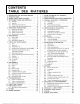
CONTENTS TABLE DES M ATIERES 1. 2. 3. 4. 5. 6. 7. 8. 9. 10. 11 . 12 . 13 . REQUESTING FOR DEALER'S SERVICE . . , SPECIFICATIONS . . . . . . . . . . . . . . . . . . .- . MAJOR PARTS IDENTIFICATION . . . . . . . . . INSTRUMENT PANEL AND CONTROLS . . . . . 4 .1 Switches . . . . . . . . . . . . . . , . - . . . . . . . 4 .2 Controls . . . . . . - . . . . . . . . . . . . . , . . . 4 .3 Hydraulic power take off . . . . . . . . . . . . . 4 .4 . Water outlet and heat indica or hole . . . . , .
' REQUESTING FOR DEALERS SERVICE " OFFRE DE SERVICE D U VENDE UR Your dealer is interested in your new tractor and has the desire to help you get the most value from it . After reading this manual thoroughly, you will find that you can do many of the regular service jobs . However, when in need of parts or major service, be sure to see your KUBOTA dealer . When in need of parts, be prepared to give your dealer both the tractor and engine serial numbers .
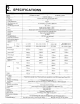
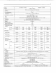
2. SPECIFICATIOIVS Model: B7100HST-D (4W D) Engine : B7100HST-E (2W D) KUBOTA D750-A Type Vertical, water-cooled, 4-cycle diesel engine Cylinders 3 Total displacement 762cm a Bare horse power and revolutions 11 .7 kW at 46 .7 r/s (16 HP at 2800 rpm) Cylinder bora and stroke 68 x 70mm Diesel fuel No .1 [below-10oC] Diesel fuel No .2 [above -10 C] Fuel Starter Electric starter with battery, glow plug and decompression device, 12V, 0.8 kW .
Model : B6100HST-D 14WD) B6100HST-E (2WD) Engine : KUBOTA D650-A Type Vertical, water-cooled, 4-cycle diesel engine Cylinders 3 Total displacement 675cm' Bare horse power and revolutions 10 .3 kW at 46 .7 r/s (14 HP at 2800 rpm) 64 x 70mm Cylinder bora and stroke Diesel fuel No . 1 [below-10° C] Diesel fuel No . 2 [above-10° C] Fuel Electric starter with battery, glow plug and decompression device, 12V, 0.
2 . SPECIFICATIONS Modele : B7100HST-D (4 roues motrices) Moteur : KUBOTA D750-A Type 87100HST-E (2 roues motrices) Vertical, refroidissement a eau, 4 temps Cyl indres 3 Deplacement totale 762cm a Puissance en cv et vitesse 11,7 kW a 293,2 rad/s (16 cv a 2800 tr/mn) Orifice du cylindre 68 x 70mm o Carburant dieselNo .1 [inferieurea-10° ] Carburant diesel No .
B6100HST-D 14 roues motrices) Modele : Moteur : B6100HST-E (2 roues motrices) KUBOTA D650-A Vertical, refroidissement a eau, 4 temps Type 3 Cylindres Deplacement totale 675cm' 10,3 kW z 46,7 rad/s I14 cv a 2800 tr/mn) Puissance en cv et vitesse 64 x 70mm Orifice du cylindre Carburant diesel No .1 (inferieure a -10° C] Carburant diesel No.
" Traveling Speeds " Vitesse de translation Traveling Speed km/h High-Low Shift Forward Low Forward High m/s g7100HST B6100HST B7100HST B6100HST -D/E -D/E -D/E -D/E 0 to 5.7 0 to 6 .5 0 to 14 .5 0 to 16 .6 Reverse Low 0 to 3 .9 Reverse High 0 to 10 .0 B7100HST-D/E B6100HST-D/E 0 to 1 .6 0 to 1 .8 0 to 4.0 0 to 4 .6 0 to 1 .1 0 to 2 .8 Rear tires 8-16 (BS) J Traveling Speed Forward Low Forward High Reverse Low Reverse H ig h P . V . avant G .V .avant P .V . G.V.
3" MAJOR PARTS IDENTIFICATION IDENTIFICATION DES PIECES PRINCIPALES Brake pedal (right) Pedale de tr e in (d r o ne) Hydraulic control lever Levier de controle hydraulique High-low gear shift lever Levier de vitesse lente et rapide Brake pedal (left) Pedale de (rein (gauche) Parking brake lever Frein a main Air cleaner Filtre a air Head lights Phares Front wheel drive lever Levier d' entrainement des roves avant (871 OOHST-D) Speed control pedal Pedale regulatrice de la vitesse de deplacement Front t
INSTRUMENT PANEL AND CONTROLS Decomp knob Bouton de decompression Engine oil pilot lamp Lampe temoin d'huile Front lamp switch Interrupteur des prares Glow lamp Lampe temoin de bougie Flasher switch Interrupteur de clignotants Horn button Bouton d'avertisseur Hour meter Compteur d'heures Charge lamp Lampe indicatrice de charge Position lamp switch Interrupteur pour lampe pour position r-i sna 4.
" Front Lamp Switch Turning the front lamp switch to the right illuminates the front lamps . " Interrupteur de Phare En tournant I'interrupteur de phare a droite allume les phares . ARRET MARCHE F-2385 " Position Lamp Switch " Interrupteur pour Lampe pour Position " Horn Button " Button d'Avertisseur Turning the key switch one click to the right then pressing the horn button (BLACK) sounds the horn .
io " Engine Oil Pressure Lamp (RED) The oil pressure lamp will glow red when the starter switch is turned on . This indicates the light and electrical wiring are okay . The light should go out after engine starts . If light remains on, stop engine and determine cause . " Charge Lamp The function of the charge lamp is to indicate if the dynamo is operating . The lamp glows red when the dynamo is not operating .
I [Sweden, Denmark, Finland, Norway] I I I Hour Meter ~ I I I " Hour Meter I This meter shows the number of hours the tractor has j been operated at rated engine rpm . The last digit (white background) indicates 1/10 of an hour . The time in minutes will be shown by multiplying by six to I last digit on white background . I Exampleoooo . . .170 hours 6 minutes used I Moving hand indicates the revolution per minute of ~ the engine .
12 4 .2 ® 05 © ® ~9 10 11 1~ CONTROLS I 4.
13 Lever de contro% hydraulique DA POlNTMORT © BAS © HAUT 10 Hydraulic control /ever AO NEUTRAL © DOWN © UP 10 " High-Low Gear Shift Lever The high-Low gear shift lever is used in conjunction with the throttle lever and the speed control pedal to determine the tractor operating speed . It has three positions "Low", "Neutral" and "High" . At "Low" position, the transmission gear engagement is for slower tractor speed and greater traction . The "Neutral" position disengages the gears .
14 " Speed Set Device (B6100HST-D/E : option) The Speed Set Device is designed for tractor operating efficiency and operator comfort . This device automatically set your operating speed . Speed set device can not be set at high speed range . ~ To engage Speed Set Device 1 . Accelerate speed to desired level using Speed Control Pedal, and move knob forward . 2 . Release Speed Control Pedal and desired speed will be maintained . ~ To disengage Speed Set Device, move knob to the "Release" position .
15 " Mid PTO A mid PTO is available for Kubota's mid mount mower (MR6000/MR48001 . When using the mid PTO, remove the shaft cover from mid PTO case . " Prise de Force Ventrale La prise de force ventrale est utilisee pour les tondeuses ventrales . Pour utiliser la prise de force ventrale, deposer le couvre-arbre du Carter .
16 " Brake Pedals (Right and left) (1) When operating the tractor on a road, be sure to inter- lock the right and left pedals as illustrated below . It will be very dangerous to use only one brake . (2) Use individual brakes to assist in making sharp turns . Disengage the brake lock and depress only one brake pedal . " Pedales de Frein (Drone et Gauche) (1) Lors de conduite du tracteur sur route, enclencher les (2) pedales de frein drone et gauche comme illustre cidessous .
17 0 Pedale de blocage du 10 Differential lock pedal " Seat The operator's seat position can be adjusted forward and backward in 120mm range by pulling the seat sliding lever. 1~ Seat ~2 Seat sliding/ever " Implement Lock Chain When transporting on the road or checking the implement in the raised position, be sure to hook one end of the implement lock chain on the chain bracket as shown in the picture so as to prevent the implement from dropping .
18 " How to Open the Bonnet " Comment Ouvrir le Capot [SAFETY PRECAUTION] ~ Never open the bonnet while the engine is running. To open the bonnet, take off the bonnet latch on the right and left sides. LCONSIGNE DE SECURITE] Ne pas ouvrir le capot en cours de marche du moteur. Pour ouvrir le capot, demonter les loquets sur les deux cStes droit et gauche . IO Loquetdecapot Bonnet latch 4 .3 HYDRAULIC POWER TAKE OFF 4 .
19 2 . To permit oil to flow into the control valve on the implement : (1) Remove the plug from the Directional Control valve assembly and connect the hose from the implement to the assembly (screw : PS%) . (2) Remove the plug from the case front cover, and connect the return hose from the implement to the cover (screw : PF'/zl . (3) Move the control lever on the tractor backwards, and turn the grip on the Directional Control valve assembly by 180° .
20 4.4 WATER OUTLET AND HEAT INDICATOR HOLE 4 .4 SORTIE D'EAU ET TROU POUR THERMOMETRE " How to Use Hot Water In order to use this model's cabin heater, take the hot water from the outlet (thread size PS 3/81, and return it to the inlet (thread size PS 3/81 . " Mode d'Emploi d'Eau Chaude Afin d'utiliser le rechauffeur en cabine de ce modele, prendre de I'eau chaude de la sortie (Dimension de filetage PS 3/8), et en ramener a I'entree (Dimension de filetage PS 3/8) .
21 OPERATING INSTRUCTIONS J " INSTRUCTIONS D'UTILISATION PRE-START CHECKS Prior to start the engine, make pre-start checks according to the Maintenance check list on page 29 . 5 .1 OPERATING THE ENGINE VERIFICATIONS AVANT LE DEPART Avant de demarrer le moteur, faites les verifications en accord au programme d'entretien de la Page 30 . 5 .1 COMMANDS [SAFETY PRECAUTIONS[ Do not start the engine in a closed room . Otherwise, the air will be polluted with exhaust gas and this is very dangerous .
z2 13) (4) Don't operate the tractor under full load condition until it is sufficiently warmed up . Don't use starting fluid to prevent the serious trouble of engine . " Starting with Dull Battery or in Cold Weather Perform the following procedure between the steps (6) and (10) on Starting : (1) Pull out the decompression knob . (2) Depress the clutch pedal all the way and turn the key switch to the start position .
23 5 .2 OPERATING THE TRACTOR 5 .2 COMMANDE DU TRACTEUR " Starting " Demarrage (1) Depress the clutch pedal to disengage the clutch . (2) Shift the high-low gear shift lever to the desired speed position . (3) Unlock the parking brake . (4) Speed up the engine by moving the throttle lever forward . (5) Slowly release the clutch pedal . (6) Depress the forward pedal with the toe of your right foot to move forward . 171 Depress the reverse pedal with the heel of your right foot to move backward .
24 [SAFETY PRECAUTIONS] (1) The only way to disengage the Speed Set Device is to move the knob to the "Release" position by hand . 121 Speed Set Device must be disengaged before depressing the reverse pedal . (3) Never use the Speed Set Device when traveling at high speed. ONSIGNEE DE SECURITE] [C111 La manii :re seule de mettre le dispositif de mise de vitesse hors fonctionnement est de deplacer la poignee a la position "Release" (declenchement) a la main .
25 5 .3 CHECK DURING DRIVING 5 .3 VERIFICATIONS PENDANT LA CONDUITS While driving, make the following checks to see that all the parts are functioning normally . Pendant la conduite fairer lee verifications suivantes afin de savoir si tour lee elements fonctionnent normalement . " Cooling Water " Eau de Refroidissement [SAFETY PRECAUTION] To remove the radiator cap, wait for about 10 minutes after stopping the engine .
26 " Urgent Stop " Arret Urgent Should the following abnormally take place, immediately stop the engine . (t 1 The engine suddenly slows down or speeds up . (21 Unusual noises are suddenly heard . (3) Exhaust fumes suddenly become very dark . 141 The engine oil pilot lamp goes on during driving . For checks and remedies in the above situations, consult your dealer for instruction . 5 .4 DIRECTIONS FOR OPERATING Dons le cas ou les phenomenes suivants se produisent, arretez immediatement le moteur .
27 C MAINTENANCE V " ENTRETIEN 6 .1 DAILY CHECK 6 .1 VERIFICATIONS JOURNALIERE To prevent trouble from occurring, it is important to know the conditions of the tractor well . Check it before starting . Pour eviter tout probleme, il est important de bien connaitre I'etat du tracteur. Verifiez le avant le depart . [SAFETY PRECAUTION] ~ Be sure to check and service the tractor on a flat place with the engine shut off and the parking brake on .
zs 6 .2 LUBRICANTS To prevent serious damage to hydraulic systems, use only KUBOTA genuine fluid or its equivalent . Place Capacity Lubricants + Engine crankcase 3.1 Q Engine oil : API Service CC or CD Below 0 ° C SAE10W or 10W-30 0 to 25 ° C SAE20 or 10W-30 Above 25° C SAE30 or 10W-30 + Hydrostatic transmission oil The oils listed below or equivalent are recommended . Maker KUBOTA SHELL Mobil Exxon Transmission 13 .5 Q Front differential case (4WD) 0 .
29 6 .3 MAINTENANCE CHECK LIST Frequency of Checks Check Points Reference Pages Initial operation (initial 60 hours) During this period, pay special attention to the following . (1) After the initial 35 hours of use, change the engine oil and clean the oil filter . (2) After the initial 50 hours of use, change the transmission oil and the oil filter cartridge and clean the strainers . (3) Sudden starting or braking should be avoided .
30 6 .3 LISTE DES VERIFICATIONS POUR ENTRETIEN Points a verifier Periodicite des verifications Pages de reference Pendant cette periode, un soin particulier sera apporte aux Rodage (premieres 60 heures) Toutes les 50 heures Toutes les 75 heures Toutes les 100 heures Toutes les 150 heures verifications suivantes : (1) Apres les premieres 35 heures d'utilisation, renouveler route I'huile pour moteur et nettoyer le filtre a huile .
31 CHECK AND MAINTENANCE " VERIFICATIOIV ET ENTRETIEN 7 .1 FUEL 7 .1 CARRURANT " Checking and Refueling [SAFETY PRECAUTION] Stop the engine before adding fuel . Keep away from sparks and flames . (1) Check the fuel level . Take care that the fuel level does not fall under the prescribed lower limit . Fuel tank capacity 13 R (10 R : steel tank type ) (2) Use high speed diesel fuel or No . 2 diesel fuel . (3) Use No .
32 A Bleeding Procedure is as Follows: La Procedure de R~amorcage est la Suivante : [CONSIGNE DE SECURITE] ~ Ne pas effectuer de purge lorsque le moteur est chaud . (1) Fill the fuel tank with fuel, and open the fuel cock . (1) Remplissez le reservoir de carburant et ouvrez le robinet de carburant. [SAFETY PRECAUTION] Do not perform bleeding when the engine is hot. 0 8/eeding screw 0 Fuel cock 0 Fuel filter pot CLOSE © OPEN (2) Twist off the bleeding screws at the top of the filter with two turns.
33 " Checking Fuel Pipe [SAFETY PRECAUTIONS] (t ) Stop the engine when attempting the check and change prescribed below . (2) Never fail to check the fuel pipe periodically . If the fuel pipe is subject to wear and aging, fuel may leak out onto the running engine, causing a fire. Although checking the fuel pipe connections is recommended every 100 service hours, it should be done every 6 months if operation does not exceed 100 hours in 6 months .
34 " Cleaning the Fuel Filter Pot When period of operation reaches approx . 100 hours, clean the fuel filter . This job should not be done in the field, but in a clean place so as to prevent dust intrusion . i11 Close the fuel filter pot cock . " Nettoyage du Corps du Filtee a Carburant Apres environ 100 heures de travail, nettoyer le filtre a carburant . Cette operation ne sera pas effectue a fair libre, mais en lieu propre pour prevenir une penetration de poussiere .
35 7 .2 ENGINE OIL 7 .2 " Oil Level Check and Replenishment (See page 2s1 " Verification du Niveau d'Huile et Remplissage (1 ) Check engine oil either before starting the engine or 5 minutes or more after the engine has stopped . (2) To check the oil level, draw out the dipstick, wipe it clean, replace it, and draw it out again . Check to see that the oil level lies between the two notches . (3) If the level is too low, add new oil to the prescribed level at the oil port .
36 " Engine Oil Filter Cartridge Change [SAFETY PRECAUTION] Be sure to stop the engine before changing the oil filter cartridge . (1) The oil filter cartridge must be changed every 150 service hours . (2) Apply a slight coat of oil onto the cartridge gasket . (3) To install the new cartridge, screw it in by hand . Over tightening may cause deformation of rubber gasket . (4) After the new cartridge has been replaced, the engine oil normally decreases a little .
37 1 .3 TRANSMISSION OIL (SAFETY PRECAUTION] Be sure to stop the engine before checking and changing the transmission oil . " Transmission Oil Check and Replenishment Draw out the dipstick atop the transmission case and wipe off oil . Then, replace it and remove it again to determine the oil level . The appropriate oil level is on the upper notch . If short, replenish through the oil port. Use hydrostatic transmission oil . (See page 28) 7 .
38 " Transmission Oil Filter Cartridge Change ® [SAFETY PRECAUTION] Be sure to stop the engine before changing the oil filters . (1) The oil filter cartridge must be changed every 200 service hours . (2) Remove the 4 bolts which secure the cover . Detach the knob of the speed set device to remove the cover . (3) Remove the oil filter cartridge by using the filter wrench . (4) Lightly tighten the screw ~A by using a screwdriver . (5) Apply a slight coat of oil onto the cartridge gasket .
39 " Cleaning Strainers (in changing transmission oil) Since the fine dust in the oil could impair the component parts of the hydraulic system precision built to withstand high pressure, the suction pipe ends are provided with oil filters . When changing the transmission oil, disassemble and rinse the oil filters with kerosene to completely clean off dust . For reassembly, take most care not to damage the parts.
40 7 .5 CHANGING FRONT WHEEL GEAR CASE (RIGHT AND LEFT)(4WD) (SEE PAGE OIL 7 .5 28) REMPLACEMENT DE ROUES (4ROUES Remove the drain and filling port plugs to discharge the used oil . After draining, replace the drain plug and fill with new oil . (DROITE 2s> If the oil is insufficient, feed the transmission oil up to the oil inlet port . HUILE 7 .6 POUR En 2G ) GREASING LE 10 POINTS BEFORE STARTING 7 .7 POINTS DE GRAISSAGE Oil or grease the following points before starting .
41 " Interlock Rod " Tige de Synchronisation Oil or grease the interlock rod and sliding holder . 1~ Interlock rod Huilez ou graissez la tige de synchronisation et le support de coulissement . ' ~ 20 Sliding holder , ~~~~~ . ` ~ ~'~~~~ ~. 0 Tige de synchronisation ~ Support de coulissement " Pedal Shafts " Axes de Pedale Grease the grease nipples on both ends of the brake pedal Graisser les raccords graisseurs sur les deux c&tes de I'axe shaft and the speed control pedal shaft.
42 7 .8 RADIATOR 7 .8 [SAFETY PRECAUTIONS] (1) Before changing the cooling water, be sure to stop the engine . (2) Do not open the pressure cap while the engine is running under heavy loads or immediately after the engine has stopped . Otherwise, hot water may spray out, scalding the operator . So make it a habit to wait for about 10 minutes before opening the cap . A full tank of cooling water is enough for one day's work . Make it a rule to check the level of the cooling water prior to operation .
43 Be sure to close the pressure cap securely . If the cap is loose or improperly closed, water may spill out and water shortage will result . (4) Radiator should be filled with 50/50 parts of antifreeze and water at all times . The anti-freeze contains a corrosion inhibitor and will allow a higher operating temperature in the radiator during the hot season . (5) Don't use an anti-freeze and a fur inhibitor at the same time . (3) Soyez stir de refermer le bouchon pression soigneusement .
44 " Anti-Freeze If the cooling water freezes, the engine cylinder and radiator may crank . In cold weather when the temperature drops below 0° C, drain out the water or add a proper amount of anti-freeze when the tractor is shut dawn . (1) There are two types of anti-freeze solutions, permanent type (PT) and semi-permanent type (SPTI . For the Kubota Engine, be sure to use the permanent type .
45 1~ Grille du radiateur 0 Radiateur O Refroidisseur d'huile Radiator net ~2 Radiator ~3 Oil cooler 7 .9 TIRE PRESSURE 7 .9 Though the tire pressure is factory-set to the prescribed level, it naturally drops slowly in the course of time . Thus, check it everday and inflate as necessary, To inflate the wheel tires, use an air compressor or hand pump . PRESSION DES PNEUS Bien que la pression des pneus soit etabl ie au niveau prescrit, elle diminue doucement avec le temps .
46 7 .10 13j (4) (5) (6) AIR CLEANER As the air cleaner uses a dry element, never apply oil . Do not let dust build up to more than a half of the dust cup . Detach the dust cup and throw away the dust-normally once a week, but everyday if working conditions are especially dusty . Do not touch the filter element except in cases where cleaning is required . When cleaning the element, refer to the instructions attached .
47 7 .11 BATTERY 7 .11 BATTERIE (SAFETY PRECAUTION] ~ Never take off the cap while the engine is running. Keep electrolyte away from eyes, hands and clothes . If you are spattered with it, wash it away completely with water. Mishandling the battery shortens the service life and adds to maintenance costs . Be sure to handle it correctly so that it will develop its full potential performance . (CONSIGNE DE SECURITE] Ne pas deboucher la batterie pendant que le moteur est en marche .
48 [CAUTIONS] 11) When connecting the battery, do not reverse the polarities . Connection with reverse polarities causes troubles to the battery and electrical system in the tractor . (2) When disconnecting the cord from the battery, start with the negative terminal first . When connecting, start with the positive terminal first. Reversing the steps may cause short-circuiting, should a screwdriver touch the terminals .
49 p ADJUSTMENTS 0 " REGLAGE [SAFETY PRECAUTION] When making adjustments, park the tractor on flat ground and apply the parking brake . 8 .1 BELT TENSION [CONSIGNE DE SECURITE] Pour effectuer les reglages, stationnez le tracteur sur terrain plat et serrez le frein a main . 8 .1 If the fan drive belt or the dynamo drive belt becomes loose, the engine may sometimes overheat, or the battery may not be charged .
50 8 .2 CLUTCH 8 .2 EMBRAYAGE Moderate clutch pedal play ranges from 2 to 4mm and moderate clutch pedal travel is 8mm . L'interval de jeu normal de la pedale d'embrayage se situe de 2 a 4mm et la course normale est de 8mm .
51 i~ Brake pedal 2t~ Brake rod ~3 Step 0 Pedale de frein ~2 Tige de fieim Repose pied ® Tendeur Ecrou d arret ~A 10 A 20mm ® Turn buckle 5~ Lock nut 10 TO 20mm 1~ Brake rod . ~2 Turn buckle 03 Lock nut 8 .4 REVERSE SPEED maximum reverse speed has been set at 10km/h, .butadjustable up to 15km/h . Loosen the lock nut . Turning . the adjusting bolt clockwise decreases the maximum reverse speed, while turning it counter. clockwise increases the speed . (3) After the adjustment, tighten the lock nut.
52 8 .5 STEERING WHEEL Moderate steering wheel play is 10 to 30mm . To adjust this, loosen the lock nut and .turn the adjusting screw to the right. After adjustment, securely retighten the nut. 8 .5 VOLANT Le jeu normal du volant est de 10 a 30mm . Pour I'ajuster, desserrez I'ecrou d'arret et tournez le boulon d'ajustage vers la drone. Apres reglage, resserrez soigneusement I'ecrou. 1~ Nut 2~ Adjusting screw 8 .
53 8 .7 IMPLEMENT LIFTING AND LOWERING LIMITS 8 .7 LIMITES DE MONTEE ET DESCENTS DE L'OUTIL The implement lifting and lowering limits can be changed by shifting the locker (A) or (B). Les limites de montee-ef descente de I'outil peuvent etre modifiees en coulissant le bloqueur (A) ou (B) .
54 8.9 EXHAUST PIPE WITH MUFFLER 8 .9 TUYAU D'ECHAPPEMENT AVEC SILENCIEUX The exhaust pipe can be rotated. Adjust this properly while the tractor operate between the crop rows . Le tuyau d'echappement peut-¬tre tourne . R~glez le correctement pendant..le travaiFde r~colte. 1~ Exhaust pipe 1~ Tuyau .
9, 9 .1 55 TROUBLESHOOTING ENGINE TROUBLESHOOTING If something is wrong with the engine, refer to the table below for the cause-and its corrective measure. Trouble Cause 1) No fuel fldws. Countermeasure ~ ~ 1) Check the fuel tank and the fuel filter, and remove dirt buildup. 2) All fuel passes through the fuel filter and much dust is caught in it . Should there be deposits on the filter, replace it .' 2) Air and water is in the fuel system .
56 9 .3 BATTERY TROUBLESHOOTING Trouble Cause `Lights have been overused until they become dim . The cell starter does not start . The cell starter does not start even after changing, and lights soon become dim . When viewed from top, the top of plates looks whitish . `Battery has not been recharged . *Charge the battery for a long enough time by the standard method, *Poor terminal connection . *Clean the terminal and tighten securely . `Battery is dead . *Renew battery .
57 PROBLEMES DE FONCTIONNEMEN~ 9 .1 PROBLEMES DE FONCTIONNEMENT DU MDTEUR Si quelque chose nest pas correct avec le moteur, referez-vous a la table ci-dessous pour la cause et sa contre-mesure. Cause Problemes de Fonctionnement 1) Le carburant n'arrive-pas . Contre-mesure 11 Verifiez le reservoir et le filtre a carburant, et retirez le depot. 2) Tout le carburant passe a travers le filtre a carburant et beaucoup d'impuretes s'y trouvent . Si il y a des depots sur le filtre, remplacez-le .
58 9 .3 PRDBLEMES DE FDNCTIDNNEMENT DE LA BATTERIE Problemes de fonctionnement Cause * Les lampes ont ete trop utilisees, jusqu'au moment ou titles deviennent faibles. Contre-mesure Mesure Preventive * Chargez la batterie pour une duree suffisamment tongue de facon standard . * Chargez la batterie correctement, ou evitez la decharge trop importante. * Le branchement terminal est mat effectue . * Nettoyez le branchement terminal et serrez-le soigneusement. *Conservez le terminal Propre et serre.
'O LONG-TERM STORAGE " STOCKAGE A LONG TERME [SAFETY PRECAUTION] When storing, remove the key from the key switch . When the tractor is not going to operate for two or three months or longer, clean stains off well and perform the following treatment before storage. (1) Repair the parts where needed . (2) Check bolts and nuts for looseness and tighten as necessary. (3) Apply grease or engine oil to the parts most likely tp rust. (4) Remove the weight .
60 '~ 11 .1 1 THREE-POINT HITCH " ATTELAGE TROIS POINTS THREE-POINT HITCH ADJUSTMENT I 11 .
61 " Check Chain The check chain serves to prevent the implement from contacting the 3-point links when the implement is rolling excessively . .lf the check chain is too taut, it takes on a full load from - the implement and is likely to break. Check chain tension should be adjusted to the extent where the lower links do not contacYthe rear wheel tires . " Tendeur Le tendeur Bert a empecher I'outil d'entrer en~contact avec les 3-points des tirants lorsque 1'outil route de fagoh excessive .
62 i' OPTIONS L " OPTIONS " Upright Muffler 166771-82517) The horizontal muffler can be converted into . an,upright muffler with minor changes of parts. To convert: (1) Remove 4 bolts (M8) fastening the elbow and muffler, then detach the stay . (2) Turn the muffler inlet upright and lock with 4 nuts (M8) . 13) Replace the horizontal exhaust pipe with an upright exhaust pipe and clamp with the band .
63 WIRING DIAGRAM I[Sweden, Denmark, Finland,Norway]I o r r a , . . . a. p I r r rr ~ ~~ n.~r ,~,..; . .. .. , "vn, nvnsvc 12V i5 always flowing . This wire is "live - even the engine slopped . rs If would cause Sparks rf it rt comes into contact with the tractor body . 12V ~s r5 Ilows when switch "ON - . Other wiring ------ Oplon Cord color : 8 = blue Ba = black Br = brown G Gpaher,amp,/a/f a a.aonsoo nme. mn rso<,amo.mm ~^O.n9Of nlama.n9bf 0.
64 J , SCHEMA ELECTRIQUE aRSR I,1/II~II F!u dgnamnr, 9a. FruOeR ",n4ory y. .r -R os .x E' a as s.fl G.RG O 0 R$ YR y fa GRSWY 6RSYR udnOmdiorn.OrvS,e GR U ~y """""~~II~~ eo~ "9 iemy .tmaouav". """"" 11 .. O-0 7 RuW q vyva"w e"" ma ye Ga Wfl9e flegubo. ea"" inedewv~~w" m ! Illt~_III ty ar 1 -le G, tourantl2V est toulours - en circulation . Ce fit est. loy0urs meme si am' de le mofeur vivant' est arrete .
WhitelYellow BlanclJaune Brown/White BrunlBlanc Head /amp 112V45/40W1 Phare l12V45/40W1 Horn Avertisseur BlueNYhite 8/eulBlanc WhitelYe/low BlanclJaune Flasher /amp l12V20W1 . Position /amp l12V5W1-left Feu clignotant l12V20W1.' Feu position (f2V5WJ-gauche Flasher /amp l12V20WJ. Position /amp 112V5Wl-right Feu clignotant l12V20W1 . Feu position l12V5W1-drone Yellow/Red Jaune/Rouge Reflector Reflecteur Flasher /amp l 12V21W1. Position /amp (12V5W1-left Feu clignotant l12V21W1.
Since its inception in 1890, Kubota, Ltd. has grown to rank as one of the major firms in Japan. To achieve this status, the company has through the years diversified the range of its products and services to a remarkable extent . Today, 19 plants and 19,000 employees produce over 1 ,000 different items, large and small . All these products and all the services which accompany them, however, are unified by one central commitment .
U.S.A. : KUBOTA TRACTOR CORPORATION 550 West Artesia Blvd ., Compton, CA 90220, U.S .A . Telephone :(2131537-2531 Western Division : 1530 East Shaw Ave., Suite 118 Fresno, CA 9 Telephone : (209)222-5226 Central Division : 13780 Benchmark Drive Farmers Branch, TX 75234 Telephone : (214)241-5900 Northern Division : 438 McCormick Blvd .