
Operation Manual


MOWER MOUNTING6
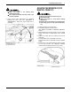
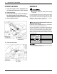
[Belt support bracket attaching and adjustment]
Adjust the belt support bracket to the following
specification with the PTO lever in the "ENGAGED"
position and tighten the belt support bracket.
To avoid serious injury:
A Make sure engine is not running.
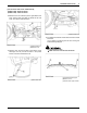
5. Remove the mower brake wire clamped under the
step.
6. After passing the mower brake wire through the wire
holder, attach it to the mower brake with the rue ring
cotter pin.
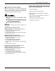
7. The mower brake is a safety device to stop the blades.
When the PTO lever is in the "DISENGAGED"
position, the brake is applied to the pulley groove and
the blade stops turning within 5 seconds. With the PTO
lever at the "ENGAGED" position, the brake is off the
pulley groove and the pulley is allowed to turn.
(1) Belt support bracket (A) Clearance between belt support
bracket and pulley. 1 to 2 mm
(3/64" to 5/64")
(B) Clearance between belt support
bracket and belt. 6 to 7 mm
(15/64" to 9/32")
(1) Mower brake wire
(2) Clamp
(1) Mower brake
(2) Wire holder
(3) Mower brake wire
(4) Rue ring cotter pin
(A) PTO lever "ENGAGED"
(B) PTO lever "DISENGAGED"