Version 1.03 (12.10.2021) Installation instruction FISTUNE DAB / DAB+ Audi MMI 3G / 3G+ Article no. 39703 www.kufatec.de Kufatec GmbH & Co. KG • Dahlienstr. 15 • 23795 Bad Segeberg • e-mail: info@kufatec.
Contents Disclaimer................................................................................................................................................. 2 Copyright................................................................................................................................................... 3 General advice.......................................................................................................................................... 3 Safety instructions............
Disclaimer Dear Buyer, our cable harnesses are developed with the help of the circuit diagrams and wiring schemes of the particular vehicle producer and they are tested and adjusted to the original vehicle before the serial production. Therefore the integration into to the on-board electric and electronic system follows the information of the vehicle producers.
Copyright Our assembly and operation manuals, assembling diagrams and additional documentation in text or picture form are protected by law. Disclosure and distribution of this documentation through print or online media is permitted only after previous written acceptance from Kufatec GmbH & Co. KG. General advice While developing this product, your personal safety combined with the best operating service, modern design and an up-to-date production technique was especially taken into account.
Safety instructions The installation can be executed only by trained qualified personnel. Before the installation disconnect the power supply. Therefore cut off the battery from the vehicle electric system, follow the manufacturer’s specification. • Never use bolts, screws and other fastening elements from car’s safety devices or steering wheel, brakes because it may influence your driving safety and cause accidents. • Connect the device only to a 12V vehicle voltage with chassis ground to the car body.
Notes NOTE: Not applicable for vehicles with an original DAB-reception (combined radio box with DAB and FM/AM/MW as well). NOTE CHANNEL SEARCH: There is no automatic channel search, it has to be done manually through MMI. A new manual channel search is necessary only for regional ensembles, when the vehicle changes the position and in this way the regional ensemble are altered too. In case of national ensembles a new channel search is not necessary.
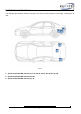
Installation instructions The following presentation shows the laying of the wires and the position of the single components as well. 3 2 1 3 2 1 Scheme 1 – (Radio box) FISTUNE Interface A4 / A5, A6 4F, A6-A7 4G.
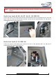
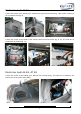
NOTE: Place the FISTUNE on a proper spot at the radio box. Consider the firm and safe seat of the box. Radio box Audi A4 8K, A5 8T, A6 4F, Q5 MMI 3G Loosen the screws of the lashing eyes and the screws behind the lever for the backrest (fig.1). The hook (fig.2) has to be bent up first and then removed. Loosen the bolt situated behind. The radio box is situated behind the left trunk lining (fig. 3). Fig. 1 Fig. 2 Fig. 3 Radio box Audi Q7 4L MMI 3G Loosen the screws of the lashing eyes.
Radio box Audi A8 4H Loosen the screws of the lashing eyes. Remove the right and left trunk lining. Take out the covering of the rear bench seat (fig. 8). Fig. 6 Fig. 7 Fig. 8 Loosen the screws of the holder of the comfort control unit and remove (fig. 9, 10). The radio box is situated directly behind (fig. 11). Fig. 9 Fig. 10 Fig. 11 Radio box Audi A6 4G, A7 4G Loosen the screws of the lashing eyes. Remove the left trunk lining.
Radio box Audi Q3 Open the maintenance door by turning the rotary handle by 90 degrees. Disconnect any plug connections and remove the maintenance door. The radio box is mounted behind the side covering in the trunk on the driver‘s side. Fig. 14 Fig.
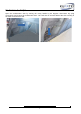
Interface connection MMI 3G/ MMI 3G+ Light conductor The connection takes place through Plug & Play on the back side of the radio box. Remove the original light conductor plugs from the radio box (fig. 14). Connect the original light conductor plug with the socket of the delivered cable harness (fig. 15). Fig. 16 Fig. 17 Integrate the light conductor of the delivered cable harness in the radio box (fig. 16). The figure 17 shows the correct connection of the interface. Fig. 18 Fig.
Antenna Connect the antenna plug to the unit. Power supply The connection of the power supply takes place with the Quadlock-plug of the radio box. The wires Brown (ground) and Red (permanent positive) have to be connected by means of a braze or a new crimp joint specifically to the vehicle (fig. 19, 20). BROWN - PIN17 RED - PIN 18 CAUTION: Do not use press-on connectors! NOTE: The wire color can also be neutral (gray). If this is the case, then please consider the wire imprint. Fig. 21 Fig.
Operation Because the FISTUNE is completely integrated in the vehicle, therefore the operation of the digital radio reception takes place through your MMI. The operation is detailed explained in the user guide of your vehicle.
Coding The coding of the vehicle is after the assembly of FISTUNE not necessary. But you can add the module to the installation list under the address 19. In order to execute the coding of the vehicle please contact your VW Audi partner. Adresse 19 Self-diagnosis Address 19 Diagnosis interface for the data bus Coding Installation list Now include the encoding "0F" in the installation list. NOTE: After the first installation press the soft key "Manually" in the MMI and start the search.