Version 1.03 (30.05.2017) Installation Instructions Complete set Active Sound incl. Soundbooster Audi A3 8V Item no. 40650 www.kufatec.de Kufatec GmbH & Co. KG • Dahlienstr. 15 • 23795 Bad Segeberg • e-mail: info@kufatec.
Contents Liability Exclusion .....................................................................................................................................2 Copy Right ...............................................................................................................................................3 General Notes ..........................................................................................................................................3 Safety Instructions ..................
Liability Exclusion Dear Customer, our cable sets are developed according to the connection- and circuit diagrams of the corresponding car manufacturer. Before the original production the cable sets will be tested on an original car. Therefore, the integration into the car electronics will be executed according to the instructions of the manufacturer.
Copy Right Our installation- and removal instructions, installation plans, software and other documentation with texts or pictures are protected by copy right. A publication or distribution of these documents is only permitted with a written approval of Kufatec GmbH & Co. KG. General Notes Regarding the development there has especially been paid attention to your personal safety together with the most possible operating comfort, modern design and actual product technologies.
Safety Instructions The installation may only be executed by trained qualified personnel. Please execute the installations only in a condition of dead voltage. Here please separate for example the battery from the main power supply and consider the instructions of the car manufacturer. • In order to not endanger your own driving safety please never use security relevant screws, bolts or other fixation pieces at steering, brake system or other components.
Notes NOTE: The use of a sound booster is not permitted without registration in the vehicle papers, in the area of the german StVZO. The noise emission of the vehicle is increased by this retrofit. The regulations of the StVZO must be observed. It is therefore recommended to ask for a specific registration option at the responsible TÜV/DEKRA office before retrofitting. Outside Germany, please observe the laws on vehicle licensing applicable in your country.
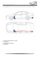
Assembly Instructions The following illustration shows the cable routing as well as the position of the individual components. 4 3 1 2 4 3 2 1 Scheme 1 – External sound generator incl.
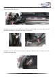
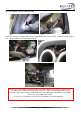
Remove the trim panels at the dashboard, fig. 1. In the next step begin the cable routing from the a-pillar on the driver’s side to the rear left, to the external sound generator. For this, remove the front sill trim which is attached with clips, fig. 2. Fig. 1 Fig. 2 Afterwards the trim panel of the b-pillar, fig. 3, and lift the rear sill trim, fig. 4. Route the cable under the trim panels according to fig. 2 and 4 in the direction of the trunk. Fig. 3 Fig.
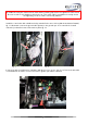
You can see the routing to the external sound generator in fig. 6 and 7. Guide the cable through the grommet outwards. Ensure a waterproofing. Fig. 6 Fig. 7 Install the external sound generator at the longitudinal beam rear left, fig. 8, and at the bumper, fig. 9, and connect it with the just routed cable, fig. 10. Fig. 8 Fig. 9 Fig. 10 Please use for the fixation of the Sound Booster suitable high tensile screws.
As additional safety the delivered steel cable and the retaining clips have to be tightened on the Sound Booster as well as at a suitable position in the car. This safety cable is an additional security should the tightening screws should be released by vibration. Install the control units with suitable workshop material in the area of the a-pillar in the driver’s footwell, fig. 11. Afterwards connect the ground cable (brown) to the ground spot.
Connect the CAN wires to the red plug of the CAN gateway according to the cable colours and Pin numbers named below. It is located below the dashboard on the driver’s side, fig. 14. To establish the connections, move the red plug off, fig. 15. Insulate the connection points afterwards! CAN High (black/white) CAN Low (black/yellow) Fig. 14 - Pin 16 (orange/black) Pin 6 (orange/brown) Fig. 15 Finally, you have to install the pushbutton for the switch of the sound profiles, e.g.