Installation Instructions Complete set active Sound incl. Soundbooster Audi TT 8J v1.2 (16.06.2017) Kufatec GmbH & Co. KG - Dahlienstr. 15 - 23795 Bad Segeberg - e-mail: info@kufatec.
Contents 1 Liability Exclusion 3 2 Copy Right 4 3 General Notes 4 4 Safety instructions 5 5 Requirements for the determinable operation 5 6 Note 5 7 How to connect a cable to another 6 8 Note Cable Inscription/Color 7 9 Assembly Instructions 8 10 Removing trim panel driver’s side 9 11 Removing lower trim panel of the dashboard 10 12 Connection CAN High & CAN Low 11 13 Connection ignition lead / ground 12 14 Removing cover parts trunk 13 15 Routing connecting cable sound generator
1 Liability Exclusion Dear Customer Our cable sets are developed according to the connection- and circuit diagrams of the corresponding car manufacturer. Before the original production the cable sets will be tested on an original car. Therefore, the integration into the car electronics will be executed according to the instructions of the manufacturer.
2 Copy Right Our installation- and removal instructions, installation plans, software and other documentation with texts or pictures are protected by copy right. A publication or distribution of these documents is only permitted with a written approval of Kufatec GmbH & Co. KG. 3 General Notes Regarding the development there has especially been paid attention to your personal safety together with the most possible operating comfort, modern design and actual product technologies.
4 Safety instructions The installation may only be executed by trained qualified personnel. Please execute the installations only in a condition of dead voltage. Here please separate for example the battery from the main power supply and consider the instructions of the car manufacturer. • In order to not endanger your own driving safety please never use security relevant screws, bolts or other fixation pieces at steering, brake system or other components.
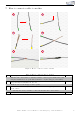
7 How to connect a cable to another 1 2 3 4 5 6 Figure 1: How to connect a cable to another No. 1 2 3 4 5 6 Table 1: How to connect a cable to another Work step Take the cable of the vehicle, to which you want to connect, (green marked here) and strip the insulation at one point with a suitable tool (cable stripper/cutter knife). Now take the cable of the cable set, which you want to connect, (yellow marked here) and strip the insulation at the end. Twirl the wires of the stripped cable together.
8 Note Cable Inscription/Color Figure 2: Cable Inscription If our cable set consists exclusively of grey wires, connect the wires according to the cable inscription. Kufatec GmbH & Co. KG - Dahlienstr. 15 - 23795 Bad Segeberg - e-mail: info@kufatec.
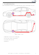
9 Assembly Instructions The following illustration shows the cable routing as well as the position of the individual components. 2,3,4 1 1 2,3,4 Figure 3: Vehicle overview • 1 External sound generator incl. mounting plate • 2 Control unit for engine sound generation • 3 Sound Booster Pro (module) • 4 Pushbutton Kufatec GmbH & Co. KG - Dahlienstr. 15 - 23795 Bad Segeberg - e-mail: info@kufatec.
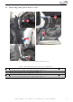
10 Removing trim panel driver’s side 2 1 4 3 5 Figure 4: Removing trim panel driver’s side Nr. 1 2 3 4 5 Table 2: Removing trim panel driver’s side - instructions Work step Loosen the lateral covering of the dashboard using a trim tool. Remove the lever for the hood release with a trim tool. Remove the trim panel of the b-pillar with a trim tool. Now loosen the sill trim using a trim tool. Remove the lower trim panel of the a-pillar with a trim tool. Kufatec GmbH & Co. KG - Dahlienstr.
11 Removing lower trim panel of the dashboard 1 2 3 4 6 5 Figure 5: Removing lower trim panel of the dashboard 2 3 Table 3: Removing lower trim panel of the dashboard - instructions Work step Remove the light switch by pressing it in on 0, then turning it to AUTO and pulling it out. Remove all three plugs from the light switch and take it out completely. Loosen the two marked screws at the bottom of the trim panel of the dashboard.
12 Connection CAN High & CAN Low 1 2 3 2 4 Figure 6: Connection CAN High & CAN Low Nr. 1 2 3 4 Table 4: Connection CAN High & CAN Low - instructions Work step Remove the air discharge installation by loosening the marked screw. Now pull the plug out of the CAN gateway. Remove the plug housing.
13 Connection ignition lead / ground 1 2 3 4 5 5 Figure 7: Connection ignition lead / ground Table 5: Connection ignition lead / ground - instructions Nr. 1 2 3 4 5 Work step Loosen the two marked screws of the fuse carrier and pull it down. Remove the back covering of the fuse carrier by loosening the three snap-fits in all. Place the cable for ignition lead (red/white) in the fuse spot 9 and protect this spot with a 15 ampere fuse afterwards.
14 Removing cover parts trunk 3 1 3 Figure 8: Removing cover parts trunk Table 6: Removing cover parts trunk - instructions Nr. 1 2 3 Work step Remove the trunk sill protection using a trim tool. Take the trunk floor out afterwards. Loosen the plugs from the cabriolet control unit (if existing) and take the inserts out of the trunk by pulling them sideways up. Kufatec GmbH & Co. KG - Dahlienstr. 15 - 23795 Bad Segeberg - e-mail: info@kufatec.
15 Routing connecting cable sound generator 2 1 2 2 3 3 Figure 9: Routing connecting cable sound generator Nr. 1 2 3 Table 7: Routing connecting cable sound generator - instructions Work step Route the connecting cable for the sound generator along the sill trim to the b-pillar. Guide the cable with a pull through aid behind the trim panel in the trunk. Pull the connecting cable out from behind and route it through the trunk to the marked grommet behind the battery. Kufatec GmbH & Co.
16 Installation sound generator 1 1 3 2 4 Figure 10: Installation sound generator 2 Table 8: Installation sound generator - instructions Work step Pull the connecting cable for the sound generator through the grommet to the underbody with a pull through aid and waterproof the grommet afterwards. Loosen the two marked screws of the impact protection. 3 Afterwards attach the sound generator with the just loosened screws.
17 Installation pushbutton 1 2 Figure 11: Installation pushbutton Nr. 1 2 Table 9: Installation pushbutton - instructions Work step Drill a hole for the pushbutton in the lower trim panel of the dashboard at the marked position. Install the pushbutton there and afterwards reinstall the entire trim panel. Kufatec GmbH & Co. KG - Dahlienstr. 15 - 23795 Bad Segeberg - e-mail: info@kufatec.
18 Important Information Sound Booster Please use for the fixation of the Sound Booster suitable high tensile screws. In order to avoid losening of the screws by vibration please make the screws safe with appropriate factory material e.g Threadlock. Please additionally check the stability of the Sound Booster regularly and if necessary retighten the screws. In case of no consideration we do not assume liability for possible damages.
List of Figures 1 2 3 4 5 6 7 8 9 10 11 How to connect a cable to another . . . . . . Cable Inscription . . . . . . . . . . . . . . . . Vehicle overview . . . . . . . . . . . . . . . . Removing trim panel driver’s side . . . . . . . Removing lower trim panel of the dashboard Connection CAN High & CAN Low . . . . . Connection ignition lead / ground . . . . . . Removing cover parts trunk . . . . . . . . . . Routing connecting cable sound generator . . Installation sound generator . . . . . . . . . .