Installation Instructions Complete Set Active Sound incl. Soundbooster Opel GT Cabrio v1.1 (24.04.2018) Kufatec GmbH & Co. KG - Dahlienstr. 15 - 23795 Bad Segeberg - e-mail: info@kufatec.
Contents 1 Liability Exclusion 3 2 Copy Right 4 3 General Notes 4 4 Safety instructions 5 5 Requirements for the determinable operation 5 6 Note 5 7 How to connect a cable to another 6 8 Note Cable Inscription/Color 7 9 Important Information Sound Booster 8 10 Assembly Instruction 9 11 Disassembly trim parts on driver’s side 10 12 Disassembly of the wheel house covering on driver’s side 12 13 Cable routing steady plus to passenger’s side 13 14 Connection Can high + Can low / Igniti
1 Liability Exclusion Dear Customer Our cable sets are developed according to the connection- and circuit diagrams of the corresponding car manufacturer. Before the original production the cable sets will be tested on an original car. Therefore, the integration into the car electronics will be executed according to the instructions of the manufacturer.
2 Copy Right Our installation- and removal instructions, installation plans, software and other documentation with texts or pictures are protected by copy right. A publication or distribution of these documents is only permitted with a written approval of Kufatec GmbH & Co. KG. 3 General Notes Regarding the development there has especially been paid attention to your personal safety together with the most possible operating comfort, modern design and actual product technologies.
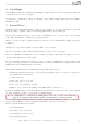
4 Safety instructions The installation may only be executed by trained qualified personnel. Please execute the installations only in a condition of dead voltage. Here please separate for example the battery from the main power supply and consider the instructions of the car manufacturer. • In order to not endanger your own driving safety please never use security relevant screws, bolts or other fixation pieces at steering, brake system or other components.
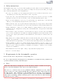
7 How to connect a cable to another 1 2 3 4 5 6 Figure 1: How to connect a cable to another No. 1 2 3 4 5 6 Table 1: How to connect a cable to another Work step Take the cable of the vehicle, to which you want to connect, (green marked here) and strip the insulation at one point with a suitable tool (cable stripper/cutter knife). Now take the cable of the cable set, which you want to connect, (yellow marked here) and strip the insulation at the end. Twirl the wires of the stripped cable together.
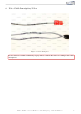
8 Note Cable Inscription/Color Figure 2: Cable Inscription If our cable set consists exclusively of grey wires, connect the wires according to the cable inscription. Kufatec GmbH & Co. KG - Dahlienstr. 15 - 23795 Bad Segeberg - e-mail: info@kufatec.
9 Important Information Sound Booster Please use for the fixation of the Sound Booster suitable high tensile screws. In order to avoid losening of the screws by vibration please make the screws safe with appropriate factory material e.g Threadlock. Please additionally check the stability of the Sound Booster regularly and if necessary retighten the screws. In case of no consideration we do not assume liability for possible damages.
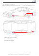
10 Assembly Instruction The following illustration shows the cable routing as well als the position of the individual components: 1 2,3 1 2,3 Figure 3: Vehicle overview • 1 Extern sound generator incl. bracket • 2 Control unit for sound generation • 3 Sound Booster Pro (module) Kufatec GmbH & Co. KG - Dahlienstr. 15 - 23795 Bad Segeberg - e-mail: info@kufatec.
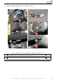
11 Disassembly trim parts on driver’s side 2 1 2 3 3 3 Figure 4: Disassembly trim parts on driver’s side No. 1 2 3 Table 2: Instructions for the disassembly of trim parts on driver’s side Work step Remove the lateral covering by using an assembly lever. Loosen and remove the lower dashboard covering, this is fastened with three marked clips. Loosen and remove the marked screws to loosen the dashboard lining. Kufatec GmbH & Co. KG - Dahlienstr. 15 - 23795 Bad Segeberg - e-mail: info@kufatec.
2 1 Figure 5: Disassembly trim parts on driver’s side No. 1 2 Table 3: Instructions for the disassembly of trim parts on driver’s side Work step Remove the covering of the centre console by using a trim tool. Loosen and remove the kickplate on driver’s side by using a trim tool. Kufatec GmbH & Co. KG - Dahlienstr. 15 - 23795 Bad Segeberg - e-mail: info@kufatec.
Disassembly of the wheel house covering on driver’s side 1 2 3 3 3 3 3 Figure 6: Disassembly of the wheel house covering on driver’s side No. 1 2 3 Table 4: Instructions for the disassembly of the wheel house covering on driver’s side Work step Note Loosen the screws at the rear wheel on driver’s side and remove it. 5xM12 Loosen and remove the two marked screws at the wheel house covering. 2xM6 Afterwards loosen and remove 14 marked clips by using an assembly lever.
Cable routing steady plus to passenger’s side 1 1 3 2 3 Figure 7: Cable routing steady plus to passenger’s side No. 1 2 3 Table 5: Instructions for the cable routing steady plus to passenger’s side Work step Please route the red/white cable for ignition plus (clamp 15) from the driver’s footwell to the centre console in the direction of the handbrake lever. Route the cable from the centre console into the footwell on the passenger’s side.
Connection Can high + Can low / Ignition plus 1 1 2 3 3 Figure 8: Connection Can high + Can low / Ignition plus No. 1 2 3 Table 6: Instructions for the connection of Can high + Can low / Ignition plus Work step Note Connect Can high + low as follows: Can high (black/white) to pin 6 (orange/black), or according to inscription. Can low (black/yellow) to pin 14 (orange-brown), or according to inscription. This port is positioned on the driver’s side.
Cable routing to the sound generator 1 2 2 3 3 Figure 9: Cable routing to the sound generator No. 1 2 3 Table 7: Instructions for the cable routing to the sound generator Work step Open the top for the following steps: Please route the cable, which comes out of the driver’s footwell, along the sill in the direction of the back wall.
Assembly sound generator 1 2 3 3 Figure 10: Assembly sound generator Table 8: Instructions for the assembly of the sound generator No. 1 2 3 Work step Fix the sound generator with the marked screws at the rear side member on the driver’s side. Fasten the safety rope through the side member and through the holder of the sound generator. Connect the plugs with the sound generator, as seen on the foto. Kufatec GmbH & Co. KG - Dahlienstr. 15 - 23795 Bad Segeberg - e-mail: info@kufatec.
Operation with the cruise control 1 2 2 Figure 11: Operation with the cruise control Table 9: Instructions for the operation with the cruise control No. 1 2 3 Work step The operation with the cruise control can be implemented in stand-modus. To change the sound profile into a next higher level, press the cruise control for 2 seconds upwards. To change into a lower sound profile, press the lever downwards.
Software 1 Figure 12: Software Nr. 1 Table 10: Notes for the software Work step If the system does not work after you have installed everything, please check by having a look on to the following Link: https://www.sound-booster.com/en/ debugging.html if everything is correct as described. For the further commissioning or debugging, our Sound Booster Software for PC / Mac should be used: Step 1: Download the appropriate software via the following link: https://www. sound-booster.com.
Software 2 1 3 Figure 13: Software Nr. 1 2 3 Table 11: Notes for the software Work step If no current vehicle is identified, you have to select the vehicle via the Manual Selection as follows: Open the dropdown-menu, search for your vehicle and select it. Click on Save Car to save the vehicle on the module permanently. If you don’t find your vehicle in this list, it is possibly necessary that the software has to be adapted to your vehicle. For this, please contact us via e-mail: info@kufatec.
Software 1 2 Figure 14: Software Nr. 1 2 3 Table 12: Notes for the software Work step You also need to check if the right ESM is selected in our software: Open the dropdown-menu, search for the correct ESM and select it. Click on Save ESM to save the ESM on the module permanently. If you, for example, has ordered a complete set with Audi control unit you need to choose as ESM 4G0 907 160 B (A6/A7.
List of Figures 1 2 3 4 5 6 7 8 9 10 11 12 13 14 How to connect a cable to another . . . . . . . . . . . . Cable Inscription . . . . . . . . . . . . . . . . . . . . . . Vehicle overview . . . . . . . . . . . . . . . . . . . . . . Disassembly trim parts on driver’s side . . . . . . . . . . Disassembly trim parts on driver’s side . . . . . . . . . . Disassembly of the wheel house covering on driver’s side Cable routing steady plus to passenger’s side . . . . . .