
Instruction Manual

10 Connection Receiver / handling
1
2 3
4
4
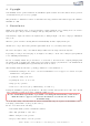
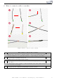
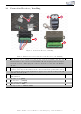
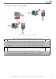
Figure 3: Connection Receiver / han d li n g
Table 2: Instruction for the Connection of the Receiver / the handling
No. Procedure Note
1 The Receiver can b e installed by plug & play between the Kufatec Module and
harness. Remove the connector from the Kufatec Module and plug it into the adapter
from the rece i ver. Then plug the connector from the receiver into the Kufatec
Module.
2 By pushing approx. 1 second the button on the left side, you can turn on or off the
sound booster. If you turn off th e sound booster the last active profile will be saved.
3 If you push the button on the rigth side for approx. 1 second, the sound profile will
switch to the next profile.
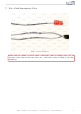
4 In case that some of the wires slip out of the Receiver, please fi nd below the exact
PIN definition:
Red wire to + (plus)
Brown wire to - (minus)
Blue/yellow wire to N01
Blue/red wire to N02
Red/green wire to CM1 & CM2
Kufatec GmbH & Co. KG - Dahlienstr. 15 - 23795 Bad Segeberg - e-mail: info@kufatec.de 9