
User Guide


12
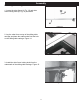
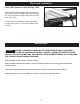
Figure 17
Installing the Sliding Table Locking Pin
1. Locate the locking pin with the black handle and
thread it through the sliding table body with wrench
as shown. Figure 17.
Assembly
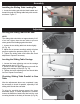
Leveling the Sliding Table to the Saw
NOTE:
The sliding table should be set approximately 3/64”
of an inch higher than the saw table to prevent
sheet goods from binding against the table.
1. Loosen the two sliding table lock knobs slightly.
(B, Fig. 18)
2. Adjust the set screws acordingly which will place
pressure against the pressure plate (A, Fig. 18)
3. Tighten the sliding table lock knobs and check
adjustment. Repeat if necessary.
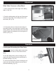
Leveling the Sliding Table Carriage
1. Loosen the lower adjusting nuts on the carriage
table support arm (A, Fig. 19).
2. Raise or lower the upper adjusting nuts until the
sliding table carriage is level (B, Fig. 19).
3. Tighten the lower adjusting nuts and check table
for level. Repeat if necessary.
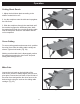
Checking Sliding Table Parallel to Saw
Table
After the adjustments above are completed it may
be necessary to check for parallel, especially if the
sliding table scrubs the saw table.
To align for parallel please repeat the steps
described above. If further adjustment is needed,
loosen the 8MM hex head bolts that hold the cast
mounting bracket to the body of the saw. (A,Fig 20)
Adjustment
A
B
A
B
A
Figure 18
Figure 19
Figure 20
A