
User Manual

PAGE
3
INSTALL AND ADJUST THE BACKREST:
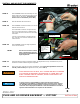
STEP 8 Refer to PIC 3. Position the assembly over the
safety strap holes; thread the hex head screws
into the holes in the frame. Torque the hex
head screws to 18-20 ft-lbs (24-27 Nm).
STEP 9 Slide the Backrest into the Receiver.
STEP 10 Refer to PIC 2. Locate the tension screw on the
backside of the Receiver.
Use a flat blade screwdriver to adjust the ten-
sion screw. Adjust the screw so that the back-
rest is firmly secured in the Receiver and easily
removable.
Turn the screw clockwise to increase the ten-
sion; turn the screw counter-clockwise to de-
crease tension.
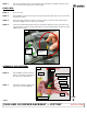
STEP 10 Refer to PIC 4. Loosen the angle adjustment
screws on the Receiver.
NOTE: The lower screw slots on both
sides of the Receiver allow for
forward and rearward Backrest
angle adjustment.
STEP 11 Adjust the Backrest angle; temporarily tighten the adjustment screws; reinstall the seat, sit on
the bike and confirm backrest angle is acceptable.
STEP 12 Remove the seat, make any necessary adjustments, then torque the adjustment screws to 8-
9 ft-lbs (10.8-12.2 Nm) and tighten set screws (refer to PIC 4).
PLUG AND GO DRIVER BACKREST — VICTORY
Ride On!
INSTALLATION
It is the end user’s responsibility to ensure that all of the fasteners
(including pre-assembled) are tightened before operation of the motorcy-
cle. Küryakyn will not provide warranty coverage on products or compo-
nents lost due to improper installation or lack of maintenance. Periodic in-
spection and maintenance are required on all fasteners.
AFTER INSTALLING THE SEAT, PULL UPWARD ON SEAT TO ENSURE
IT IS LOCKED IN POSITION. WHILE RIDING, A LOOSE SEAT CAN
SHIFT CAUSING LOSS OF CONTROL, WHICH COULD RESULT IN
DEATH OR SERIOUS INJURY.
PIC 4
FRONT OF BIKE
ADJUST BACKREST ANGLE
TO DESIRED FIT
LOOSEN ADJUSTMENT
SCREWS. ADJUST
BACKREST ANGLE;
TORQUE ADJUSTMENT
SCREWS AND
TIGHTEN THE SET
SCREWS
PIC 3
FRONT OF BIKE