Operating Instruction and Parts Manual for KPT 36/48 Walk Behind Power Trowel 12010 Dairy Ashford Road, Suite 160 Sugar Land, TX 77478 281-313-2506 • 800-469-4178
TABLE OF CONTENTS Contents ……………………………………………...…1 FOREWARD Forward …………………………………………...…… 2 • For your own safety and protection from bodily injuries, carefully read, understand and follow the safety instructions in this manual. Feature…………………………….......................………2 Specification ………………………….................………2 Safety precautions …………………………………...… 3 Maintenance record ……… ……………………....……4 Maintenance schedule…………................................……5 Operation elements………..........................
SAFETY PRECAUTIONS 3 1. Before starting operation, the operator has to check that all control and safety devices function properly. 2. Always keep unauthorized, inexperienced, untrained people away from this machine. 3. Rotating and moving parts will cause injury if contacted. Make sure guards are in place. Keep hands and feet away from moving parts. 4. The engine must always be stopped before attempting any repair or adjustments. Ignition switch should be off. 5.
MAINTENANCE SCHEDULE Each use Routine Service Intervals General Inspection: Guards Warning Stickers Test Run Controls: Dead-Man Switch Operation Pitch Control Assembly Engine: Engine oil Engine Oil Filter Oil Cooler Cooling Fins Air cleaner Air Intake Line Fan Belt Valve Clearance Fuel filter Fuel Tank Engine wiring Drive Train: Clutch/Pulley Operation Spider plate assembly V-Belt Blades Gearbox: Gearbox oil Gearbox Breathers Check Check After 1.
Model 350WSB & 350WSB With Stand Parts List OPERATION (Finishing) When starting the finishing operation, never set the trowels up over 1/4" pitch. After the floating operation, the first thing to do is to remove the floating disc from the blades. Clean the blades, spider plate and disc from cement paste collected during the floating operation. Increase the blade pitch up to a maximum of 1 cm for the first finishing operation and then continue to increase the pitch on the following finishing operations.
e. Pull the starter grip lightly until you feel resistance, then pull briskly. Return the starter grip gently. CAUTION! Do not allow the starter grip to snap back against the engine. Return it gently to prevent damage to the starter. 3. Stopping the engine a. Move the throttle lever to the SLOW position. c. Turn the fuel valve lever to the OFF position. 4. Setting engine speed Position the throttle lever the desired engine speed. f.
LUBRICATION 1. Engine oil lever check Check the engine oil level with the engine stopped and in a level position. 1. Remove the filler cap/dipstick and wipe it clean. 2. Insert and remove the dipstick without screwing it into the filler neck. Check the oil level shown on the dipstick. 3. If the oil level is low, fill to the edge of the oil filler hole with the recommended oil. 4. Screw in the filler cap/dipstick securely. 2. Engine oil change Drain the used oil while the engine is warm.
AIR FILTER SERVICE A dirty air filter will restrict air flow to the carburetor, reducing engine performance. If you operate the engine in very dust areas, clean the air filter more often than specified in the MAINTENANCE SCHEDULE. WARNING! Never use gasoline or low flammable point solvents for cleaning the air cleaner element. A fire or explosion could result.
6. TROWELS TURN, ENGINE AT IDLE • Idle too fast • Belt too tight 9 • Clutch seized • Pulley out of alignment 7. TROWELS BLADES WEARING UNEVENLY • Spider plate seized • Adjusting screws (carriage bolts) incorrectly set • Arms bent • Floating disc not evenly attached to the blades 8.
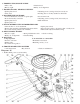
KPT 36 Power Trowel Part List Item Part No. Part name 1 36001 Handle assembly 2 36002 3 Handle Part List Qty Item Part No.
2. Handle assembly 3.
4.Gearbox assembly 5 Spider plate assembly Gearbox Part List Item 1 2 3 4 5 6 7 8 9 10 11 12 13 14 15 16 17 18 19 20 21 22 23 24 25 26 27 28 29 Part No.
Spider Plate Part List Item 1 2 3 4 5 6 7 8 9 10 11 12 13 14 15 16 17 18 19 20 Part No. 36501 36502 36503 36504 36505 36506 36507 36508 36509 36510 36511 36512 36513 36514 36515 36516 36517 36518 36519 36520 6 Clutch assembly Part name Qty Spider plate 1 O-ring 30×2.
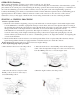
Diagram - 48 1. Walk-behind power trowel assembly 2.
KPT 48 Power Trowel Part List Handle Part List Item Part No.
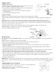
3. Deadman switch assembly 5 Spider plate assembly 4.
Gearbox Part List Item 1 2 3 4 5 6 7 8 9 10 11 12 13 14 15 16 17 18 19 20 21 22 23 24 25 26 27 28 29 Part No.