OperatingInstruction and Parts Manual for Tamping Rammer KRM160 12010 Dairy Ashford Road, Suite 160 Sugar Land, TX 77478 281-313-2506 • 800-469-4178
TABLE OF CONTENTS WARNING 2 : This manual provides information regarding the operation and maintenance of these products. We have made every effort to ensure the accuracy of the information in this manual. We reserve the right to change this product at any time without prior notice. Please keep this manual available to all users during the entire life of the Vibratory Rammer. 1.FORWARD………………………………………………………….............................…………………1 2.EMISSION CONTROL SYSTEM INFORMATION………………………..............
2. EMISSION CONTROL SYSTEM INFORMATION 3 Source of Emissions The combustion process produces carbon monoxide, oxides of nitrogen and hydrocarbons. Control of hydrocarbons and oxides of nitrogen is very important because, under certain conditions they react to form photochemical smog when subjected to sunlight. Carbon monoxide does not react in the same way, but it is toxic.
EMISSIONS COMPONENT DEFECT WARRANTY COVERAGE This emission warranty is applicable in all States. Our Corporation (located at 12010 Dairy Ashford Road, Suite 160 Sugar Land, TX 77478) warrants to the initial retail purchaser and each subsequent owner, that this non-road engine(herein "engine") has been designed, built and equipped to conform at the time of initial sale to all applicable regulations of the U.S.
Model 350WSB & 350WSB With Stand Parts List If you have any questions regarding your warranty rights and responsibilities, you should contact our CORPORATION Product Support Department for the information. THINGS YOU SHOULD KNOW ABOUT THE EMISSION CONTROL SYSTEM WARRANTY: o MAINTENANCE AND REPAIRS You are responsible for the proper maintenance of the engine. You should keep all receipts and maintenance records covering the performance of regular maintenance in the event questions arise.
3.1.12 ALWAYS wear protective clothing appropriate to the job site when operating equipment. 3.1.13 ALWAYS wear hearing protection when operating equipment. 3.1.14 ALWAYS keep hands, feet and loose clothing away from moving parts of the machine. 3.1.15 ALWAYS use common sense and caution when operating the machine. 3.1.16 ALWAYS be sure the rammer will not tip over roll, slide or fall when not being operated. 3.1.17 ALWAYS turn the engine OFF when the rammer is not being operated. 3.1.
3.
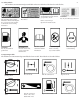
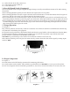
3.5 Safety Labels The machines use international pictorial labels where needed. These labels are described below: This molded-in label contains important safety and operating information. If it becomes illegible, the cover must be replaced. Refer to the Parts Book for ordering information. CAUTION! Use only clean, filtered gasoline fuel. For optimal control, performance and minimal hand/arm vibration, grasp handle as shown.
4. TECHNICAL DATA 4.1 Rammer Model Engine type Engine Engine power(KW/HP) Weight (KG/LBS) Jumping strike(max)cm(in) Impact force(max)KN plate size(cm) Fuel Tank L Impact number(per minutes) Shipping size(L*W*H)(cm) 9 KRM160R Air-cooled single cylinder Robin EH12-2D 3.0/4.0 85 6.5(2.6) 10 30*31 2.8 450-650 77*55*107 KRM160H 4-stroke Honda GX160 4.0/5.5 88 4.2 Sound Measurements Products are tested for sound pressure level in accordance with EN ISO 11204.
5.5.1 Place throttle in the idle position (c3). 5.5.2 Turn engine switch to‘‘OFF’’(d). 5.5.3 Close fuel valve (e). 10 5.6 Low Oil Shutoff Switch (if equipped) The low oil shutoff switch is designed to prevent engine damage caused by an insufficient amount of oil. When starting the machine. oIf the warning light flashes quickly once this indicates the engine oil level is acceptable.
6. MAINTENANCE 6.1 Periodic Maintenance Schedule 11 Maintenance, replacement or repair of the emission control devices and systems may be performed by any non-road engine repair establishment or individual. Daily before starting After first 5 hours Every week or 25 hours Every month or 100 hours Every 3 months or 300 hours Every Year Check fuel level. Check engine oil level. Inspect air filter. Replace as needed. Check oil level in sight glass. Check fuel line and fittings for cracks or leaks.
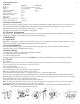
Graphic 5 6.2.5 Cleaning. 6.2.5.1. Clean the air filter elements if they are to be reused. Paper air filter element. Tap the filter element several times on a hard surface to remove dirt or blow compressed air[not exceeding 207 kPa(2.1 kgf/cm2,30 psi)] through the filter element from the inside. Never try to brush off dirt, brushing will force dirt into the fibers. Foam air filter element. Clean in warm soapy water, rinse and allow to dry thoroughly. Or clean in non-flammable solvent and allow to dry.
Graphic 7 13 Oil change: 6.4.5 Unscrew the oil drain plug (e) located below the oil sight glass. 6.4.6 Tip the rammer back until it is resting on its handle and allow oil to drain. Note: In the interests of environmental protection, place a plastic sheet and a container under the machine to collect any liquid which drains off. Dispose of this liquid in accordance with environmental protection legislation. 6.4.7 Screw in the oil drain plug (e). Torque to 54 Nm. 6.4.
6.7 Troubleshooting Problem/Symptom Engine does not start or stalls. Engine does not accelerate, is hard to start or runs erratically. Engine overheats. Engine runs rammer does not tamp. Engine runs, rammer operation is erratic. On machines equipped with the low oil shutoff switch, the warning light flashes slowly, the engine starts but shuts off after 10-12 seconds.
6.
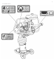
NO. Description Qty NO. Description Qty 1 ENGINE 1 34 CONNECTING ROD 1 2 NUT M10 4 35 HEXAGONAL BOLT M6x25 8 3 FLAT WASHER Φ10xΦ28x1.