
Installation Guide
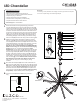

Illustration 03
Illustration 01
INSTALLATION SHEET
CH14348
LED Chandelier
START FROM HERE
•
Make sure power is completely off at the fuse box.
•
Have your fixture installed by a qualified licensed electrician
•
Prepare everything in a clear area.
•
Wear gloves at all times during this installation.
•
Read instructions carefully before you start assembly.
•
Keep this instruction sheet for future reference.
Technical Support: 1-855-855-8926
Please Note:
• For dimming, an ELV (Electronic Low Voltage) or a TRIAC type of dimmer is required
• For use on a sloped ceiling, use included angle adaptor
19054 28th Avenue Surrey, BC Canada V3S 6M3
T: 604 538 7162 TF: 1-855 85 KUZCO F: 604 538 7196
W: kuzcolighting.com
20181207
Female ends
You have now completed the installation of your fixture,
enjoy.
Select the hanging height of the fixture by adding or removing
extension rods (2e) from the hardware package. Determine how
much wire (2f) is needed from the hub (3a) to the DC driver in the
canopy (2a). Depending on the length of the extension rods used,
provide 7” of extra wire for connection up to the DC Driver
(Shorten the wires if required)(DO NOT CUT WIRE SHORTER
THAN 23” when using 12”+ 4” rods for the minimum hanging
height). Using the 12” rod first with both female ends(See
Illustration 03), connect each rod (2e) starting from the hub going
clockwise while pushing the wires (2f) through each rod until you
reach the angle adaptor (2c). Before connecting the wires (2f) to
the driver, make sure to insert the canopy cover (2d) through the
rods (2e). Once the rods are fully connected and wires are pulled
into the canopy, connect the wires to the DC driver by using the
wire connector (2g) provided. Black to black and white to white
(See Illustration 02 and refer to the diagram on the driver).
Lastly, attach the canopy cover to the canopy by turning
clockwise.
1.
3.
2.
Next, attach the LED spoke (3b) to the center of the fixture hub
(3a). Push in the LED spoke to the hub and secure with set screws
(3d) provided. Install the quick connector from the hub (3a) to LED
connector in the spoke (3b) (See Illustration 01) and push extra
wires back to the hub. Slide the diffusers (3e) in the spokes and
secure using the endcaps (3c) (use a rubber mallet if necessary,
not provided). Repeat assembly for the remaining spokes.
4.
Remove the fixture from its original packaging. Secure the
mounting plate (1c) to the junction box (1a) with the screws (1d)
provided in the hardware package. Remove the driver cover (2d)
and the canopy end cover (2h) from the canopy by turning counter
clockwise. Connect all wires from the driver to the wires from the
junction box correctly G ground to ground, N neutral wire (white to
white), L live wire (black to black) with provided wire connectors
(1b). Align the holes in the canopy (2a) to the threaded holes in
the mounting plate (1c). Push the canopy up towards the ceiling.
Use the screws (2b) to secure the canopy onto the mounting plate.
3a.
2e.
12”
2d.
3a.
1a.
1b.
1c.
1d.
2a.
2c.
2e.
3b.
2g.
2b.
3c.
3e.
3d.
2f.
V+
V-
DC
Driver
Illustration 02
+
-
L
N
White
Black
Low Voltage
120V
Black
White
2h.