KUZMA STOGI REF 313VTA TONEARM Instruction manual 2009-11 Serial Number: …..
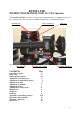
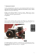
KUZMA LTD INSTRUCTION MANUAL FOR 313 VTA tonearm The Stogi Ref 313VTA tonearm is a very precisely engineered piece of equipment, however, the construction is robust and requires minimal maintenance for optimal performance. azimuth lock VTA tower&knob VTA lock Fig.1 Ring fixing Cueing device adjust.
General description : The whole construction is mounted on a rigid VTA tower which allows very precise VTA adjustment while playing, without any loss of rigidity, yet with up to 0.01 mm of precision and zero play. The main tube is constructed and machined from solid aluminium, similar to our tangential Air line arm. The main counterweight balances the tonearm. Azimuth can be adjusted in small repeatable increments with zero play, by means of an Allen key.
1. Unpacking Open the box carefully and remove the top covers. First remove the armbase and prepare it for fixing onto the turntable. Be sure that the armboard on the turntable has the correct cut-out (main central hole must be 40 mm in diameter). 2. Basic set up Armbase: Mount the armbase on the turntable. If the pre-cut has a thread, then use three screws and fix them from the top through the armbase into the armboard thread.
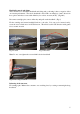
Headshell removal and fixing: This tonearm has a detachable headshell and fixing and positioning it has no negative effect on tonearm performance. The whole headshell is fixed with one Allen key 2 mm. Insert it in the top hole and release screw with Allen key for at least one turn (ACW). (Fig.2&3) Disconnect cartridge pins, remove Allen key and pull out the headshell. (Fig.4) Fix the cartridge and return headshell back in to the tube.
4. Adjustment of tracking force Balance the tonearm with the tracking scale, which must be at record height. Rotate the counterweight towards the tube to increase tracking force. Rotating the counterweight for one red dot changes tracking force for approximately 0.15 g. Check that the cueing device is at the correct height (see paragraph 9)! 5. Adjustment of tangential geometry Put a record on the platter and adjust VTA in such a way, that the central axis of the tube will be parallel to the record.
. Adjustment of azimuth To make azimuth adjustments, release the two screws locking the mechanism at the centre top of the main tonearm tube, with Allen key 2mm. Under the main tube is a tiny rod with a hexagonal screw. Insert the Allen key 2 mm into the screw (it may feel loose), rotate it slightly and it will alter the azimuth. (Fig.1) Rotating it back will bring azimuth to its previous position. Changes can be seen by misalignment of the white lines on the top of the centre of the tube.
9. Cueing device adjustment Should you find that in the ‘up’ position the cartridge is too high or too low above the record then the cueing device can be raised or lowered. This can be done simply by using Allen key 1.5 mm: Insert key into screw on side of arm rest. Release screw, raise or lower device and retighten. Rotation of cueing device can affect the drift of cartridge while travelling vertically down. The cueing device may lift slightly as the screw is retightened.
APPENDIX 1 Tangential Cartridge geometry adjustment Once the cartridge has been mounted, it is necessary to ensure that the cartridge is tangential to the record grooves in order to minimize tracking distortion during playing. As the cartridge moves in an arc across the record, tracking distortion occurs and is minimized by the tonearm geometry and the angle of the cartridge in the headshell.
To rotate or readjust cartridge: 4. Slightly loosen the screws which attach the cartridge to the headshell. 5. Holding headshell in one hand slightly rotate the body of the cartridge. 6. Recheck alignment at position A and continue adjustment until line described in point 3 is achieved. 7. Alignment at zero point 121 mm (B): Reposition protractor and check alignment at position B. Fig. 15 Alignment at B 8.
10. Now rotate protractor and again position stylus at zero point A as described in 5 and 6 above, ensuring that the position of the cartridge in the slots alongside is not changed but only rotated for alignment of the cantilever in zero point A. (Fig.17) Fig.17 Rotation at A 11. Recheck alignment of the cantilever at zero point B. If cantilever is not aligned here, rotate protractor to find where on line “x- y” the cantilever is aligned again. (Fig.18&15) Fig.
Appendix 2 Fine Azimuth Adjustment This can be done using an oscilloscope and a test record or by using good records in a good system and listening to the sound. Cartridges with fine profiles (VDH, Microline etc.) are more sensitive to this adjustment. On the other hand cheaper cartridges are not made so well, making fine adjustment more useful. With an oscilloscope we measure the differences in crosstalk between both channel. The idea is that on both channels this is equally small.
Appendix 3 Fine bias adjustment 1. Set bias and tracking force as previously described and listen to mistracking on highly Modulated tracking bands on test record. On higher modulated bands mistracking can be heard as impure tones and there will be more overtones. (See instructions on test record) 2. If mistracking is apparent, increase or decrease bias until minimum mistracking is found.
A X Y B X Y S Cartridge Protractor ( Not in correct scale) Tonearm mounting protractor 14