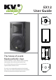
EX12 User Guide The future of sound. Made perfectly clear. At KV2 Audio our vision is to constantly develop technologies that eliminate distortion and loss of information providing a true dynamic representation of the source. Our aim is to create audio products that absorb you, place you within the performance and deliver a listening experience beyond expectation.
CONTENTS INTRODUCTION 3 HOW TO USE THIS MANUAL 3 Icons used include: 3 Introducing the EX12 3 Electronics 3 Acoustic Components 4 Enclosure Design 4 APPLICATIONS 4 AC POWER 4 CHAPTER 1: AC POWER REQUIREMENTS 5 Voltage Requirements 5 The Power Connector 5 Current Requirements 5 AC Cable Color Coding 6 IIMPORTANT SAFETY INSTRUCTIONS 6 SAFETY SUMMARY 6 The EX12 Control Panel 7 Audio Input and Output 7 Chapter 2: Audio Signal 7 Amplifiers and Acoustic Filters 7 LED Status
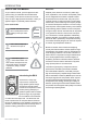
INTRODUCTION HOW TO USE THIS MANUAL Electronics As you read this manual, you’ll find figures and diagrams to help you understand and visualize what you’re reading. You’ll also find numerous icons that serve as cues to flag important information or warn you against improper or potentially harmful activities. Amplifier power, electronic crossovers, phase alignment, equalization, time correction and speaker protection are integrated into the EX12’s amplifier module.
INTRODUCTION Acoustic Components KV2 Audio has developed a revolutionary woofer technology called Trans-Coil™. The woofer has two coils, a standard voice coil assembly and a second coil placed directly on the neodymium magnetic circuit’s pole piece. This technology eliminates voice coil in ductance resulting in a flat impedance response above the resonance point and achieves faster transient response through increased force and control of the moving mass.
CHAPTER 1: AC POWER REQUIREMENTS Voltage Requirements The EX12 operates safely and without audio discon tinuity if the AC voltage stays within the operating window of 100V-120V in 115V mode, 205V-240V in 230V mode and 225V-260V when working in 250V mode, at 50 or 60Hz. CAUTION: If the On LED does not illuminate or the system does not respond to audio input, remove AC power immediately. Verify that the voltage is within the proper range.
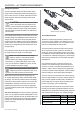
CHAPTER 1: AC POWER REQUIREMENTS AC Cable Color Coding If the colors referred to in the diagram don’t correspond to the terminals in your plug, use the following guidelines: Connect the blue wire to the terminal marked with a N or colored black. Connect the brown wire to the terminal marked with an L or colored red. Connect the green and yellow wire to the terminal marked with an E or colored green or green and yellow. into your outlet, consult an electrician for replacement of the obsolete outlet. 11.
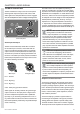
CHAPTER 2: AUDIO SIGNAL The EX12 Control Panel The EX12 features an easy to use rear control panel featuring audio input and output, level control, LED status lights and a low pass filter that can be engaged when the loudspeaker is used as a stage monitoring device. 0 POWER ON/ LIMITER SIGNAL / THERMAL – 6dB LEVEL + 6dB The audio source must be capable of producing a minimum of 20 dB volts (10 volts rms into 600 ohms) to produce the maximum peak SPL over the operating bandwidth of the loudspeaker.
CHAPTER 2: AUDIO SIGNAL operating level. This type of protection allows the phase response of the system to remain unchanged as the level is lowered. Buy not compressing or limiting peak signal, dynamics also remain unchanged. The control objective is to regulate the operating temperature of the transducers magnetic circuits log term. This ensures no impact on performance due to power compression and allows the components to retain their ability to reproduce high dynamics.
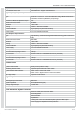
APPENDIX A: EX12 SPECIFICATIONS AND DATA Conforms to the following Product Specifications Safety: EN 60065: 2002 IEC 60065: 2001 EMC: EN 55103-1: 1997 emission(1) EN 55103-2: 1997 immunity(2) This device complies with the requirements of the Low Voltage Directive 73 / 23 / EEC and the EMC Directive 89/336/ EEC. This device also complies with EN 55103-1 & -2.
APPENDIX A: EX12 SPECIFICATIONS Magnetic Circuit Active Impedance Control Second Static Voice Coil Yoke Mounted – Copper Clad Aluminum High Frequency Amplifier Specifications Type Class AB – Push Pull – Low Intermodulation Design Metal Oxide Silicon Field Effect Transistor (MOSFET) output stage Transformer Balanced Speaker Output Yes Rated Continuous Power 50 Watts Distortion <.
APPENDIX A: EX12 SPECIFICATIONS Construction Features Basic Geometric Design Asymmetrical Geometry Material 15mm Exterior Grade Baltic Birch Finish Ultra Wear Resistant Black Polymer Coating Hardware One (1) Each Recessed Top Handle One (1) Each Recessed Side Handle One (1) Each “M10” Top Hang Point Omnimount bracket points on Top and Side Two (2) Each Integrated “M10” Side Hang Points One (1) Each 1.
The future of sound. Made perfectly clear. At KV2 Audio our vision is to constantly develop technologies that eliminate distortion and loss of information providing a true dynamic representation of the source. Our aim is to create audio products that absorb you, place you within the performance and deliver a listening experience beyond expectation. KV2 Audio, Nádražní 936, 399 01 Milevsko, Czech Republic Tel. +44(0)1423 816868 www.kv2audio.