
Satellite TV System User Manual

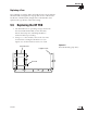

6. Connect the new antenna gyro’s Molex connector
to the main PCB.
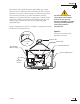
7. Replace the antenna gyro gasket (see Figure 5-8).
8. Using the standoffs and washers removed in
Step 3, secure the new antenna gyro to the
reflector bracket. The antenna gyro should be
oriented so that the cable extends from the top of
the gyro, as shown in Figure 5-8.
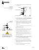
9. Using a tie-wrap, secure the antenna gyro cable to
the bottom right standoff.
10. Reattach the counterweight, screws, and washers
removed in Step 2.
11. Redress the gyro and RF cables using tie-wraps.
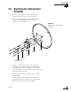
12. Carefully move the reflector through its range of
motion to ensure that the cable moves freely
between the elevation mechanism and the lower
assembly. Adjust the antenna gyro cable as
necessary to ensure proper motion.
13. Reinstall the PCB cover.
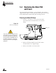
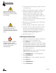
Calibrating the Antenna Gyro
1. With a PC connected to the ADCU’s maintenance
port, apply power to the antenna unit.
2. Type
HALT<cr> (<cr> indicates a carriage
return/ENTER key) while the system is performing
the limit switch initialization routine. The system
will complete the initialization function by finding
the azimuth and elevation switch limits and then
go to the home position.
IMPORTANT! Record the 8-digit serial number
displayed in the startup message.
3. Type
DEBUGON<cr> to enter Debug Mode.
4. Type
CLEAREE<cr>.
5. Type
ZAP<cr> to restart/reinitialize the system.
6. Type
HALT<cr>.
7. Type
DEBUGON<cr>.
8. Type
=TVG4HP<cr>.
54-0147
112
TracVision G4 Technical Manual
When rotating the antenna by
hand, go slowly! Hitting the
mechanical stops with excessive
force will damage the azimuth limit
switch.
Refer to
Section 4.6, “Computer
Diagnostics” on page 98
for
complete details on connecting a
PC to the system via the
maintenance port.
Make sure the cable passes
through the PCB access slot to
protect the wires from the edge of
the PCB frame.