Satellite Television A Guide to TracVision LF/SF owner’s manual • KVH TracVision LF/SF • Installation Instructions User’s Guide Technical Manual ® •
TracVision LF/SF Owner’s Manual Addendum (ECO # 6857) The following information applies to Revision D of the TracVision LF/SF Owner’s Manual (KVH Part Number 54-0194). The DISH 500 mode, in which the SAT SELECT button switches between the two DISH 500 satellites, has been changed to make it easier to use. The following instructions have been updated to reflect this change. 3.5 DISH 500 Operation The DISH 500 service offers programming on two different satellites (Echo 119 and 110).
4. Press the switchplate’s SAT SELECT button for 1 second. When you release the button, the Status indicator starts flashing while the antenna searches for another satellite. 5. When the switchplate’s Status indicator fully illuminates again, check the signal strength meter. If the meter turns green and indicates “Locked– Echostar 119,” proceed to step 6. If the meter stays red, repeat step 4. 6.
Congratulations! You have selected one of the most advanced land-mobile satellite tracking systems available today. KVH® Industries’ TracVision® LF/SF is designed for use with DIRECTV®, DISH Network™, and ExpressVu. This manual provides detailed instructions on the proper installation, use, and maintenance of your TracVision LF/SF system. Before using this manual, be sure to check the inside back cover for any addenda, which may detail changes to the manual’s information.
TracVision® and KVH® are registered trademarks of KVH Industries, Inc. DIRECTV® is an official trademark of DIRECTV, a unit of GM Hughes Electronics Corporation. DISH Network™ is an official trademark of EchoStar Communications Corporation. ExpressVu is a property of Bell ExpressVu, a wholly owned subsidiary of Bell Satellite Services.
Table of Contents 1 Introduction . . . . . . . . . . . . . . . . . . . . . . . . . . . . . . . . .1-1 1.1 Digital Satellite Television . . . . . . . . . . . . . . . . . . . . . . . . . . . . . . .1-1 1.2 System Overview . . . . . . . . . . . . . . . . . . . . . . . . . . . . . . . . . . . . . .1-1 1.2.1 TracVision LF/SF Components...............................................1-2 1.2.2 Integrated Receiver Decoder (IRD) ........................................1-2 1.
3.2.1 Using the IRD for Satellite Selection ......................................3-3 3.2.2 Using the Switchplate for Satellite Selection ..........................3-3 3.2.2.1 The Status Indicator . . . . . . . . . . . . . . . . . . . . . . . . . . . . .3-4 3.3 Turning Off the System . . . . . . . . . . . . . . . . . . . . . . . . . . . . . . . . .3-4 3.4 Watching Television . . . . . . . . . . . . . . . . . . . . . . . . . . . . . . . . . . . .3-4 3.5 DISH 500 Operation . . . . . . . . . . . . . . .
5 Maintenance . . . . . . . . . . . . . . . . . . . . . . . . . . . . . . . .5-1 5.1 Warranty/Service Information . . . . . . . . . . . . . . . . . . . . . . . . . . . .5-1 5.2 Preventive Maintenance . . . . . . . . . . . . . . . . . . . . . . . . . . . . . . . . .5-1 5.3 Replaceable Parts . . . . . . . . . . . . . . . . . . . . . . . . . . . . . . . . . . . . . .5-2 5.4 Field Replaceable Unit Procedures . . . . . . . . . . . . . . . . . . . . . . . .5-3 5.4.1 PCB Removal and Replacement...........
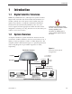
Introduction 1 Introduction 1.1 Digital Satellite Television DIRECTV®, DISH Network™, and ExpressVu systems transmit digital audio and video data from land-based transmitters to a satellite “parked” above the equator. Each satellite relays the signals in spot beams covering the continental United States. TracVision LF/SF automatically identifies, locks onto, and receives signals from the appropriate satellite.
A Guide to TracVision LF/SF 1.2.1 TracVision LF/SF Components The antenna unit includes the antenna positioning mechanism, signal front end, power supply and control elements. The antenna is a parabolic dish mounting a dual-output low noise block (LNB) converter with built-in preamplifier. A molded ABS radome encloses the baseplate and is secured in place with standard fasteners. Connectors on the back of the baseplate join the power, signal, and control cabling from units inside the vehicle. 1.2.
Introduction 1.3.1 Additional Materials Required for TracVision LF/SF Use To make full use of your new TracVision LF/SF and receive satellite TV, you will need to provide/purchase the following: • Television • Appropriate IRD for your selected satellite TV service 54-0194 Rev. D You can purchase and/or activate an IRD directly from KVH! Call KVH at 1-888-584-4163 for details.
Installation 2 Installation TracVision LF/SF is designed for simple installation and setup. Just follow these easy steps: Step Refer to Section... 1. Choose the antenna location 2.1 2. Mount the antenna unit 2.2 3. Connect the system components 2.3 4. Activate the IRD 2.4 5. Check out the system 2.
A Guide to TracVision LF/SF 2.1 Choosing the Best Location • Since the TracVision antenna requires a clear view of the southern sky to receive satellite signals, the ideal antenna site has an unobstructed view of the horizon/satellite all around. • Keep the antenna clear of any obstructions on the roof (e.g., air conditioners). The antenna requires a 15º to 75º look angle to receive satellite signals.
Installation 2.2 Mounting the Antenna Unit 1. Make sure that you have chosen a suitable mounting location based upon the guidelines in Section 2.1, “Choosing the Best Location.” 2. Remove the antenna unit from its shipping carton. 3. At the bottom of the antenna baseplate, cut the tie-wrap and pull it out of the baseplate. Then seal the two holes with the plugs provided in the kitpack. The tie-wrap secures the antenna’s LNB for shipping (as shown in Figure 2-3).
A Guide to TracVision LF/SF 5. Using the four mounting plates as templates, drill 20 3⁄16" holes through the roof of the vehicle. 6. Apply construction adhesive to the bottom of the antenna’s four mounting plates. If using a liquid construction adhesive, apply beads to the mounting plates in a zig-zag pattern. If the roof’s mounting surface is not perfectly flat as KVH recommends, make sure the baseplate does not warp when you attach the antenna’s mounting plates. Refer to Section 2.
Installation 2.3 Connecting System Components The following sections provide instructions for properly wiring the antenna unit to the components inside the vehicle. Locating the Switchplate Before running cables, you need to determine the location for the TracVision LF/SF switchplate. 1. The switchplate should be installed in a dry, flat location within reach of the cables that will connect to the antenna unit. 2. Once you’ve decided on a suitable location, create a panel cutout in the mounting surface.
A Guide to TracVision LF/SF Figure 2-7 Switchplate Connectors Input Power (+12 VDC) Ground IRD Ground Wire Switchplate Mounting Hole (1 of 2) RJ11 Jack (Data Cable to IRD - Optional) Data/Power Connector Maintenance Port (DB9 Connector) 2.3.1 Connecting the Antenna to the Switchplate 1. Connect one end of the antenna data/power cable to the antenna’s data/power connector and lock in place (see Figure 2-6). 2.
Installation Installing Two IRDs and TVs To connect a second TV and IRD to the TracVision LF/SF system, you must connect a second RF cable to the antenna’s RF2 connector (see Figure 2-6). Route the other end of the RF cable down into the vehicle and connect it directly to the second IRD. Connecting Three or More IRDs and TVs To install three or more IRD/TV pairs, an active multiswitch (Channel Master model 6214IFD or equivalent) must be placed between the antenna unit and the IRDs.
A Guide to TracVision LF/SF 4. Terminate all unused output connectors with 75 ohm DC blocks (Channel Master #7184, Radio Shack #15-1259 or equivalent). 2.3.3 Sealing the Cable Access Hole Once the RF and data/power cables are connected to the antenna, you need to seal and cover the cable access hole to protect against leakage. 1. Completely seal the cable access hole with silicone sealant or RTV. 2.
Installation 2.3.5 Connecting the Switchplate to Vehicle Power The switchplate must be connected to a +12 VDC, 2.5-3.5 amp power supply to operate. 1. Disconnect vehicle power by removing the appropriate vehicle fuse. 2. Run a cable from vehicle’s power (11-16 VDC) out through the switchplate panel cutout. 3. Connect the power cable to the switchplate’s power terminals as shown in Figure 2-7.
A Guide to TracVision LF/SF 2.4 Activating the IRD KVH makes it easy to activate your IRD. Just call KVH at 1-888-584-4163 and ask for IRD Activation (Monday - Friday, 8:30 a.m. - 5:00 p.m. EST). For other options, please refer to the user manual that accompanied your IRD. Note that EchoStar IRDs that have not been activated within several months of manufacture require additional steps to complete the process. Refer to Appendix D for complete details. 2.
Installation Message Definition KVH TracVision Displays for 5 seconds at startup Software Version Current software version Alternates with “KVH TracVision” Initializing System initializing Search Mode 1 Antenna unit in Search Mode 1 Search Mode 2 Antenna unit in Search Mode 2 Search Mode 3 Antenna unit in Search Mode 3 Reacquisition System is reacquiring the satellite RF Signal Error RF signal detector has no signal at input AZ Motor Error Fault detected in azimuth drive subassembly EL
A Guide to TracVision LF/SF 2.5.2 Checking Out the System Without an IRD Data Connection To ensure that the system is configured and operating properly, you will need to check the data provided in the system’s startup routine. To do so, you need to connect a PC to the antenna baseplate’s maintenance port. The diagnostics procedure requires terminal emulation software such as Windows Hyperterminal or PROCOMM. Use the settings appropriate to your application. 1.
Installation 3. Press the switchplate’s POWER button to apply power to the TracVision LF/SF system and wait for the system to fully initialize. Data should be scrolling on the PC display to identify any system problems detected. If no data is seen, recheck your connections and the terminal software setup. 4. After completing the review of the startup and operational routines, shut down the system. 2.
Using Your TracVision LF/SF 3 Using Your TracVision LF/SF For TracVision LF/SF to receive the satellite signals, the antenna must have a clear line of sight to the satellite. If you only receive intermittent signals or the antenna cannot find the satellite, check around your vehicle for any objects that could be blocking the signal, such as trees, buildings, highway overpasses, etc.
A Guide to TracVision LF/SF 3. Press the switchplate’s POWER button, as pictured in Figure 3-2. Figure 3-2 Switchplate Front Panel Status Indicator Power Button Sat Select Button These features only active if the system is NOT connected to an IRD low-speed data port 4. (TracVision LF only) If the vehicle is moving, avoid turning for 60 seconds after turning on the antenna to allow the antenna gyro to initialize properly.
Using Your TracVision LF/SF 4. If your TV does not show a clear picture, the antenna is tracking the wrong satellite. Refer to Section 3.2.2, “Using the Switchplate for Satellite Selection,” for instructions on selecting a different satellite. 3.2 Tracking the Correct Satellite If your system is connected to an IRD’s low-speed data port, follow the steps in Section 3.2.1, “Using the IRD for Satellite Selection.
A Guide to TracVision LF/SF 3.2.2.1 The Status Indicator If your system is not connected to an IRD’s low-speed data port, the switchplate’s Status LED indicates the antenna’s current condition. Table 3-1 describes this LED’s four conditions. Table 3-1 Status Indicator Conditions LED Condition Meaning OFF Initializing, please wait ON Tracking a satellite Slow Flashing Searching for a satellite, please wait Fast Flashing System error, see Section 4, “Troubleshooting” 3.
Using Your TracVision LF/SF Cable Unwrap The antenna unit can rotate a full 720° before coming to the end of its cable. If it does so, the system automatically unwraps the cable by quickly rotating the dish in the opposite direction. During this process, your television transmission will be frozen momentarily while the cable unwraps and the antenna reacquires the satellite.
A Guide to TracVision LF/SF 3. When the switchplate’s Status indicator fully illuminates (stops flashing), check the signal strength meter on the TV. If the meter turns green and indicates “Locked–Echostar 119 West,” skip to step 6. 4. Press and hold the switchplate’s SAT SELECT button for 1⁄2 second. The Status indicator starts flashing while the antenna searches for another satellite. 5. When the switchplate’s Status indicator fully illuminates again, check the signal strength meter.
Troubleshooting 4 Troubleshooting The troubleshooting matrix shown in Table 4-1 identifies some trouble symptoms, their possible causes, and references to troubleshooting solutions. SSI BLE CAU Blo wn SE fuse (AN DS or im Dew OLU p or r rop TIO ain er w N) poo Sat i r i ng ling ellit (Se e si on d c t i on gna ome Sat 4.1. l blo ellit (Se 1) cke e co c t d i on 4 vera (Se Veh . c 1 g t icle .2) i on e is sue 4.1. turn 3) ing (Se Inco c d tion urin rrec g st 4.1.
A Guide to TracVision LF/SF 4.1.1 Blown Fuse or Improper Wiring If the antenna unit is installed but entirely non-responsive, there are two key factors to check as part of the troubleshooting process: 1. Blown Fuse – The antenna unit is equipped with a fuse mounted on its CPU Board. If this fuse has blown or been broken, the antenna unit will not operate. Refer to Section 5.4.1, “PCB Removal and Replacement,” for details on the fuse location and how to access the CPU Board. 2.
Troubleshooting 4.1.4 Satellite Coverage Issue TracVision LF/SF will provide outstanding reception throughout the entire coverage area for your satellite television service of choice. However, signal quality can be degraded as you approach the fringe coverage areas. Refer to your satellite television service manual to check the viable coverage area. 4.1.
A Guide to TracVision LF/SF 4.2 IRD Troubleshooting The IRD that was provided with your satellite television service may also be the cause of less-than-ideal operation. 4.2.1 IRD Wiring Refer to Section 2.3, “Connecting System Components,” and your IRD user manual to confirm that the IRD is properly connected to the antenna unit and the television. 4.2.
Troubleshooting 4.2.5 Failed IRD Status Check As detailed in Appendix E, TracVision LF/SF completes a detailed startup routine whenever it is turned on. One of the first checks is the IRD status test. As noted in the typical startup cycles, the expectation is that the IRD and its communications link to TracVision LF/SF will pass this test. There are, however, two alternate results, each indicating a slightly different problem.
A Guide to TracVision LF/SF 4.3 Antenna Gyro and LNB Faults Section 5, “Maintenance,” provides detailed instructions for authorized service personnel who may be required to replace TracVision LF/SF components. The TracVision SF does not include an antenna gyro. 4.4 Most terminal emulation programs have a parameter for local character echo. Select this parameter to see what is being typed without any system delay.
Troubleshooting 2. Open the terminal emulation software and establish the following settings: • Bits per second: 9600 • Data bits: 8 • Parity: None • Stop bits: 1 • Flow control: None 3. Apply power to the TracVision LF/SF system and allow the system to complete full initialization. Data should be scrolling on the PC display to identify any system problems detected. If no data is seen, recheck your connections and the terminal software setup. 4.
Maintenance 5 Maintenance The following sections provide details on preventive maintenance and field replaceable units and parts for the TracVision LF/SF antenna unit. 5.1 Warranty/Service Information For information on KVH warranty, repair, and liability policies, please refer to the complete warranty statement provided at the conclusion of this manual. If you have any questions, please call your local authorized dealer or installer, or contact KVH directly.
A Guide to TracVision LF/SF 5.3 The serial number of your TracVision LF/SF will be required during any troubleshooting or service calls. You will find the serial number on the inside front cover of this manual. Replaceable Parts TracVision LF/SF has been designed with durability and low maintenance in mind. If you experience an operating problem or otherwise require technical assistance, contact your local authorized TracVision LF/SF dealer/installer first.
Maintenance 5.4 Field Replaceable Unit Procedures The following subsections provide detailed procedures for repairing or swapping out field replaceable units. The procedures refer to labeled items presented on the following diagrams. Pan Head Screws Always lift the antenna unit by the gray baseplate, never by the radome or any portion of the antenna assembly! Figure 5-1 Antenna, PCB, and Rotating Plate PCB Cover 3.
A Guide to TracVision LF/SF Figure 5-3 Antenna Assembly TracVision LF only Antenna Gyro Cable Wing Screw and Washer Locking Nuts and Washers Reflector Bracket LNB Clamp LNB Antenna Gyro Antenna Gyro Gasket Figure 5-4 Rotating Plate Azimuth Motor Cable Clamp and Screw PCB Antenna Gyro Cable (TracVision LF only) 5-4
Maintenance 5.4.1 PCB Removal and Replacement Estimated Time to Repair: 1⁄2 hour The microprocessor PCB assembly is protected by a cover fastened to the rotating plate – Fig. 5-1. The cover must be removed to gain access to the main power fuse and the PCB assembly. 1. Using needle-nose pliers, remove the E-ring from one end of the connecting rod – Fig. 5-2. 2. Remove the connecting rod by sliding it off the bracket.
A Guide to TracVision LF/SF Figure 5-6 PCB Connector Locations – Rear View Limit Switches Fuse Cable Wrap Gyro (TracVision LF only) J4 PCB J11 J2 RF Connector to IRD RF Connector to LNB J1 Elevation Motor Azimuth Motor 7. Remove the 9 pan head screws securing the PCB to the rotating plate. 8. Reverse this process to install the replacement PCB. Reinstall all cable connectors removed in Step 6. When replacing the PCB cover, be careful not to pinch any cables. 9.
Maintenance 4. Remove 6 pan head screws from the PCB cover flanges. 5. Remove the PCB cover. To get the necessary clearance, rotate the linear actuator up 90º while lifting the PCB cover – Fig. 5-5. 6. Remove the screw and clamp holding the cable to the rotating plate; save the cable clamp for reuse – Fig. 5-4. 7. Remove the Molex connector from J11 on the CPU board – Fig. 5-6. 8. Remove the 4 locking nuts and flat washers and take the antenna gyro off the bracket. 9. Remove the antenna gyro gasket. 10.
A Guide to TracVision LF/SF 5.4.3 Antenna LNB Replacement Estimated Time to Repair: 1⁄2 hour The LNB receives preamplifier operating power from the IRD via the PCB – Fig. 5-3 and 5-4. Be certain that the IRD is disconnected from its power source before removing or reconnecting the LNB. 1. Disconnect both RF coaxial connectors at the LNB. 2. Remove the wing screw and washer from the LNB clamp – Fig. 5-3. 3. Remove the top of the LNB clamp – Fig. 5-3. 4. Remove the LNB.
Maintenance 8. Record the Cold Sky Average and the RFGAIN value reported in Step 7. 9. Type ZAP. The system will re-initialize using the new RFGAIN and RFOFFSET scale factors displayed following Step 7. 10. Wait for the system to perform the background noise calculation. Read the Average Noise Level value from the messages transmitted out the maintenance port. This value must be greater than 300 and less than 1300.
A Guide to TracVision LF/SF 5.5 Preparation for Shipment If you need to repack the antenna unit for shipment, you must first secure the LNB. Follow the steps below to repack the antenna unit. When rotating the azimuth mechanism by hand, go slowly! Hitting the mechanical stops with excessive force will damage the azimuth limit switch. Figure 5-7 Baseplate Shipping Restraint Holes 1. Remove the radome. 2.
System Specifications Appendix A System Specifications Physical Characteristics Power 11-16 volts DC @ 2.5 amps nominal, 3.5 amps peak Dimensions/Weight 32" wide x 14.8" high, 33 lbs LNB Dual Output Tracking (TracVision LF only) Better than 30º/sec Maintenance Port 9600 bps, 8,N,1,EIA, RS232 Table A-1 TracVision LF/SF System Specifications Pointing System Elevation Range 15º to 75º Azimuth Range 720º Position Repeatability 0.
Comprehensive System Wiring Diagram Appendix B Comprehensive System Wiring Diagram The wiring diagram is presented on the following page. 54-0194 Rev.
VEHICLE
Switchplate Template Appendix C Switchplate Template 2" 2.5" 54-0194 Rev.
EchoStar IRD Activation Procedure Appendix D EchoStar IRD Activation Procedure If you have purchased a DISH Network system, there is a chance that your EchoStar IRD will fail to acquire the satellite when you first activate it. This has been known to happen in IRDs that have not been activated within several months of their manufacture.
A Guide to TracVision LF/SF 10. Type in the elevation that you obtained in Step 6. - Type EL,xxx (e.g., Elevation of 30.2° = EL,302) 11. Using a compass, take a bearing on an object that is approximately on the azimuth obtained in Step 6. 12. Type in an azimuth that points the antenna in the direction of the object selected in Step 11. The Signal Strength Meter is located on the bottom of the “Point Dish and Signal Strength” Screen.
Startup Data Sequences Appendix E Startup Data Sequences The data on the following pages presents the startup data sequences registered by the TracVision LF/SF. The first part of each section shows the sequences registered by a system that is connected to an IRD low-speed data port. The second part of each section shows the sequences registered by a system that is NOT connected to an IRD low-speed data port. Both parts show two routines.
A Guide to TracVision LF/SF Satellite Found: AZ = +POS: 53.6 36.5 62.26, EL = 36.50, RF = 1300 449 *** Entering Tracking *** +POS: 61.8 36.5 1260 +POS: 62.2 36.3 1346 +POS: 64.0 36.5 1716 *** Entering Satellite Check *** +POS: 64.3 --------Confirming proper satellite lock 36.1 1747 Satellite Located IRD Signal Quality = 54 +POS: 66.1 35.6 1522 +POS: 64.6 35.5 1749 IRD Signal Quality = 58 +POS: 66.2 36.1 1467 “Instant On” Startup Sequence ?PGM KVH TracVision LF Rev X - Version X.
Startup Data Sequences E.1.2 System Not Connected to IRD Data Standard Startup Sequence ?PGM KVH TracVision LF Rev X - Version X.
A Guide to TracVision LF/SF +POS: 331.7 33.4 2153 Switch held: wrong satellite--------------SAT SELECT switch pressed Exclude: No longer search AZ = 331.7, EL = 33.4 *** Entering Search Mode 1 *** -----------Searching for a different satellite Search1 decided to go to: AZ = 335.9, EL = +POS: 23.5 +POS: 162.5 33.5 33.5 518 33.5 1105 *** Entering Search Mode 2 *** +POS: 150.5 +POS: 80.1 +POS: 180.0 33.4 1108 33.4 889 34.0 1092 *** Entering Search Mode 3 *** +POS: 180.0 34.3 873 +POS: 22.
Startup Data Sequences VEL_INDEX: Az = 1996, El = 2182 ----------Expected range is 1700-2300 RATE BIAS: PASS --------------------------Az & El values above are within valid ranges *** Initializing Finetune *** +POS: 360.0 23.1 1575 Signal Peaked: AZ = 0.00, EL = 22.50, RF = 1919 *** Tracking Satellite *** +POS: 360.0 22.5 1917 +POS: 360.0 22.5 1976 Switch held: wrong satellite--------------SAT SELECT switch pressed Exclude: No longer search AZ = 0.0, EL = 22.
A Guide to TracVision LF/SF E.2 TracVision SF Sequences E.2.1 System Connected to IRD Data Standard Startup Sequence ?PGM KVH TracVision SF Rev X - Version X.XX - Serial Number XXXXXXXX Limit Switch Test Limit Switch Status: PASS-----------------PASS is expected *** Initializing IRD *** .. IRD STATUS: PASS identification DSS --------------------PASS is expected with successful IRD Saved Sat Pos: EL = 33.4 *** Averaging Background Noise *** +POS: 45.0 26.6 +POS: 57.9 20.0 1004 735 +POS: 232.
Startup Data Sequences “Instant On” Startup Sequence ?PGM KVH TracVision SF Rev X - Version X.XX - Serial Number XXXXXXXX Instant On --------------------------------System skips limit switch test Limit Switch Status: PASS-----------------PASS is expected *** Initializing IRD *** ... IRD STATUS: PASS DSS --------------------PASS is expected with successful IRD identification Saved Sat Pos: EL = 33.3 *** Initializing Finetune ***-------------Peaking the satellite signal +POS: 360.0 33.
A Guide to TracVision LF/SF Switch Back to Echostar IRD Type IRD STATUS: FAIL None -------------------FAIL is expected with no IRD data connection Saved Sat Pos: EL = 33.5 *** Averaging Background Noise *** +POS: 45.0 26.3 762 +POS: 62.1 20.0 1111 +POS: 223.5 20.0 1082 Average Noise Level = 985 Nor = 1826 Saved Sat Pos: EL = 33.5 *** Entering Search Mode 1 *** +POS: 193.4 30.1 1098 +POS: 205.8 33.5 878 Satellite Found: AZ = 330.0, EL = +POS: 0.9 +POS: 331.2 33.5 33.
Startup Data Sequences *** Tracking Satellite *** +POS: 348.8 23.3 2100 +POS: 348.8 23.3 1840 Saved Sat Pos: AZ = 348.76, EL = +POS: 348.8 23.3 2190 +POS: 348.8 23.3 2010 23.29 “Instant On” Startup Sequence ?PGM KVH TracVision SF Rev X - Version X.
A Guide to TracVision LF/SF Switch Back to Echostar IRD Type IRD STATUS: FAIL None Saved Sat Pos: EL = 22.5 *** Averaging Background Noise *** +POS: 45.0 +POS: 62.1 +POS: 223.5 26.3 956 20.0 1094 20.0 850 Average Noise Level = 965 Noise Threshold = 1794 Saved Sat Pos: EL = 22.5 *** Entering Search Mode 1 *** -----------Searching for a different satellite +POS: 193.4 22.5 869 +POS: 205.8 22.5 1083 Satellite Found: AZ = 350.6, EL = +POS: 15.0 22.5 471 +POS: 354.0 22.5 620 22.
Maintenance Port Parser Commands Appendix F Maintenance Port Parser Commands TracVision LF/SF system parser commands are parsed when the system receives an ASCII carriage return (Hex 0D). An ASCII line feed (Hex 0A) is permitted but is ignored in any transmitted command. All system responses are terminated with an ASCII carriage return followed by a line feed and ending with either an acknowledge character (ASCII > (Hex 3E)) or a not-acknowledge character (ASCII ? (Hex 3F)).
A Guide to TracVision LF/SF F.2 Manual Positioning Commands To execute the following commands, first put the antenna unit in idle mode by typing HALT and pressing “ENTER.” Positioning commands may be entered after the antenna comes to rest.
Maintenance Port Parser Commands Azimuth CCW Step Function: commands a 0.1 deg CCW manual step in azimuth angle Command: 4 Argument: none Response: echoes the command Elevation UP Step Function: commands a 0.1 deg UP manual step in elevation angle Command: 8 Argument: none Response: echoes the command Elevation DOWN Step Function: commands a 0.1 deg DOWN manual step in elevation angle Command: 2 Argument: none Response: echoes the command F.
A Guide to TracVision LF/SF F.
KVH Industries Limited Warranty TracVision LF/SF Limited Warranty on Hardware KVH Industries, Inc. warrants the KVH product purchased against defects in materials for a period of TWO (2) years and against factory labor costs for a period of ONE (1) year from the date of original retail purchase by the original purchaser.
KVH Industries, Inc. 50 Enterprise Center • Middletown, RI 02842 • U.S.A. Phone: +1 401 847-3327 • Fax: +1 401 849-0045 • E-mail: info@kvh.com • Internet: www.kvh.com KVH® and TracVision® are registered trademarks of KVH Industries, Inc.