Installation Guide TracPhone V7 TracPhone V7 24" (60 cm) Configuration
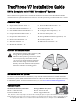
TracPhone V7 Installation Guide KVH’s Complete mini-VSAT Broadband sm System These instructions explain how to install the TracPhone V7 mini-VSAT Broadband satellite communications system. Instructions on how to use the system are provided in the User’s Guide. Installation Steps 1. Inspect Parts and Get Tools... 3 9. Wire the Belowdecks Units... 13 2. Plan the Antenna Installation... 4 10. Connect Power... 15 3. Plan the Belowdecks Installation... 5 11. Configure the Computer(s)... 16 4.
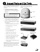
1 Inspect Parts and Get Tools Before you begin, follow these steps to make sure you have everything you need to complete the installation. Figure 1: TracPhone V7 System Components Antenna a. Unpack the box and ensure it contains everything shown in Figure 1 and on the Kitpack Content Lists. Save the packaging for future use. Radome IMPORTANT! Always lift the antenna by the baseplate and never by the radome or any portion of the internal antenna assembly (see Figure 1). Baseplate b.
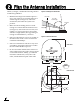
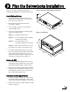
2 Plan the Antenna Installation Before you begin, consider the following antenna installation guidelines: • • Figure 2: Blockage from Obstruction Minimize blockage. The antenna requires a clear view of the sky to transmit and receive satellite signals (see Figure 2). The fewer obstructions, the better the system will perform. Make sure the mounting surface is wide enough to accommodate the antenna’s base (see Figure 3).
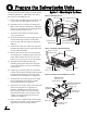
3 Plan the Belowdecks Installation Before you begin, consider the following installation guidelines for the belowdecks units. Control Unit and Modem • Select a mounting location in a dry, wellventilated area belowdecks away from any heat sources or salt spray. • Be sure the front panels will be easily accessible to the user. • Leave enough room at the rear panel for connecting the cables.
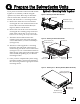
4 Prepare the Belowdecks Units If you plan to mount the control unit and modem inside the optional 19" (482.6 mm) case, follow these steps to assemble the case. a. Remove the four M4 screws securing the rear cover to the case. Discard the rear cover. b. Attach the top cover to the case using four M4 x 12 mm screws (see Figure 6). Attach the bottom cover and the two mounting brackets using four M4 x 16 mm screws. c. Attach the four plastic feet to the bottom cover (see Figure 6). d.
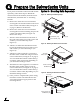
4 Prepare the Belowdecks Units If you plan to mount the control unit and modem together as an assembly, without using the optional case, follow these steps to detach the rack-mount brackets, attach the strain-relief bracket, and attach the “L” mounting brackets. Option 2 - Mounting Units Together Figure 9: Detaching the Rack-Mount Brackets Control Unit #6 Washer (x12) #6-32 Screw (x12) a.
4 Prepare the Belowdecks Units If you plan to mount the control unit and modem separately, follow these steps to detach the control unit from the modem, attach the strainrelief brackets, and attach the “L” mounting brackets. Option 3 - Mounting Units Separately Figure 12: Detaching the Retaining Straps a. Remove the 12 #6-32 screws and washers securing the rack-mount brackets to the front of the control unit and modem (see Figure 9 on page 7). Remove the brackets. Co ntro it Mo dem b.
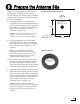
5 Prepare the Antenna Site Once you have identified a suitable antenna mounting site, according to the guidelines provided in Step 2, follow these steps to drill the mounting holes and cable access hole to prepare the site for installation. a. Unfold the antenna mounting template (supplied in the Customer Welcome Kit) and place it onto the mounting surface. Make sure the “FWD” (forward) arrow points toward the bow and is parallel to the vessel’s centerline (see Figure 15).
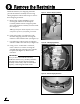
6 Remove the Restraints Inside the antenna, four shipping restraints prevent the antenna assembly from moving during shipment. Follow these steps to remove these shipping restraints. a. Remove the six #10-32 Phillips screws securing the radome to the baseplate. Carefully lift the radome straight up until clear of the antenna assembly and set it aside in a safe place.
7 Wire the Antenna Follow these steps to connect the data, power, and RF cables to the antenna. a. In addition to the data and power cables, you will need to connect two 75-ohm RF coax cables from the antenna to the belowdecks equipment. Use the guidelines in Figure 20 to determine the type of RF cables required.
8 Mount the Antenna Follow these steps to mount the antenna to the mounting surface. Figure 22: Forward Arrow in Antenna Baseplate a. Place the antenna baseplate over the holes drilled in the mounting surface. b. Make sure the forward arrow inside the baseplate points toward the bow and is parallel to the vessel’s centerline (see Figure 22). c. Make sure the four holes in the baseplate line up with the four holes in the mounting surface.
9 Wire the Belowdecks Units Wire the Antenna Cables Figure 25: Antenna Power and Data Wiring Follow these steps to connect the antenna to the control unit and the modem. Antenna NOTE: A system wiring diagram is provided in Appendix A on page 27. Terminal Strip Connector 1 a. First dress the data and power cables from the antenna. Strip back the insulation of each wire approximately 1/4" (6 mm) and gently twist each wire to ensure a good electrical connection.
9 Continued Wire the Belowdecks Units Figure 28: Modem Data and BUC Power Wiring Follow these steps to connect the control unit to the modem. Control Unit Wire Colors: Body/Stripe Wire the Control Unit to the Modem Modem MODEM RS422 BUC Power BUC POWER 20V 2.5A a. Connect a serial data cable from the “Modem” jack on the control unit to the “ACU” jack on the modem (see Figure 28). b. Connect the BUC power cable from the “BUC Power” jack on the control unit to the “BUC Pwr” jack on the modem.
10 Connect Power Follow these steps to connect power to the TracPhone V7 system. a. Before you begin, disconnect vessel power. Figure 31: Power Wiring Control Unit AC Input CAUTION For your own safety, disconnect vessel power and make sure the circuit is dead before you connect any power cables. b. Be sure the vessel is properly grounded in accordance with marine standards. c. Connect the control unit and modem to the supplied AC power strip (see Figure 31 and Figure 32).
11 Configure the Computer(s) Follow these steps to configure the user’s computer(s) for a wired Ethernet connection to the TracPhone V7. Once you have set up and tested a wired connection, you can configure the computer(s) for a wireless connection. Figure 33: Windows Vista - Local Area Connection Properties IMPORTANT! When setting up a wireless network, apply security settings, such as encryption, to protect the network from outside intrusion.
11 Continued Configure the Computer(s) Windows XP Figure 35: Windows XP - Local Area Connection Properties a. Turn on the networked computer. b. At the Windows Contol Panel, double-click Network Connections. You can find the control panel either through the Start menu or “My Computer.” c. At the Network Connections window, double-click the Local Area Connection icon for the Ethernet connection you are using for TracPhone V7. d. At the Local Area Connection Status window, select the General tab.
11 Continued Configure the Computer(s) Macintosh OS X a. Turn on the networked computer. b. At System Preferences, click the Network icon. c. At the Network window, select the following: • Show: Built-in Ethernet • Configure: Using DHCP • Leave all text boxes blank d. Network: Click Apply Now. e. Restart the computer.
12 Turn On the System Follow these steps to turn on the TracPhone V7 system and check the system for proper operation. Figure 38: Power Switches Power Switch Control Unit a. Ensure the antenna has a clear, unobstructed view of the sky. b. Apply vessel power to the TracPhone system, including the router, MTA, and remote service & support module. c. Turn on the power switch on the front of the the modem (see Figure 38). The button’s light should illuminate green. d.
13 Set Up RF Hazard Zones (Optional) To prevent exposure to RF energy, which may be harmful to people who stand within 36 feet (11 meters) of the antenna, you can configure up to two RF radiation hazard zones for areas where crew and/or passengers frequent (see Figure 41). The system will disable the transmitter whenever the antenna is pointing within one of these zones.
14 Test the System Now that you have installed the system, you can test the system to verify it is ready for customer delivery. Follow the steps below to test the system for proper operation. Figure 44: Technician Testing the TracPhone V7 System a. With the TracPhone system powered on, restart the customer’s networked computer(s). b. Make sure the control unit display indicates the system is “Online.” c.
14 Continued Test the System f. Open the web browser on any wired (not wireless) networked computer and enter the following address to access the modem’s system status web page: http://192.168.0.1 g. At the login window, enter the following user name and password: User name: KVH (all caps) Password: None (leave blank) h. At the system status web page, make sure Signal Quality is at least 8 dB Eb/No (see Figure 46).
15 Educate the Customer The installation process is complete! Before you depart the vessel, give the Customer Welcome Kit to the customer and explain how to use the system. Also be sure the customer understands the following: • The antenna transmits RF energy that is potentially harmful. Whenever the system is powered on, make sure everyone stays more than 36 feet (11 meters) away from the antenna within its 5-80° look angle (see Figure 47).
Appendices This section provides a system wiring diagram and supplemental instructions for terminating an LMR-400-75 cable. Contents A. Wiring Diagram... 27 B. Terminating LMR-400-75 Cable...
A Wiring Diagram Appendix Antenna Terminal Strip Connector 1 2 3 4 5 6 7 8 9 10 11 12 Note: Terminals #3 and #8 are not used MRx Power Red Black MTx Data White/Gray Gray/White White/Orange Orange/White White/Brown Brown/White White/Blue Blue/White Control Unit Power GP10 Serial Service Module Power Power SIM Antenna On/Off Audio Modem J1 AC PWR J3 Rx RF J6 BUC PWR J2 Tx RF J5 CONSOLE MODEL: VMBR-1510 ArcLight PART: 1234567 REV XXX SERIAL: XX-XXXXXX CAGE CODE: 12345 J4 ACU J8 U
B Terminating LMR-400-75 Cable These instructions explain how to terminate an LMR-400-75 RF cable with an EZ-400-FMH-75 “F” connector using the tools from the TK-400EZ-75 tool kit. For more detailed instructions, refer to the Times Microwave website (www.timesmicrowave.com). Appendix Figure 49: Cutting the Cable a. Using the CCT-01 cutting tool, cut the cable evenly (see Figure 49). b.
B Continued Terminating LMR-400-75 Cable e. Using a utility knife, carefully remove any residual plastic from the center conductor, if necessary (see Figure 53). f. Figure 53: Removing Plastic Residue Insert the end of the cable into the #2 end of the ST-400EZ stripping tool (see Figure 54). Then rotate the tool clockwise around the cable until the tool turns easily. This removes the cable jacket from the end of the cable, exposing the braid and dielectric (see Figure 55). g.
B Continued Terminating LMR-400-75 Cable h. Gently flare the braid with your fingers (see Figure 57). i. Insert the end of the cable into the connector body until the dielectric is firmly seated inside the connector (see Figure 58). Be sure all braid wires remain on the outside of the connector. j. Trim any excess braid (see Figure 59), if necessary. The braid should assemble flush to within 1/16" (1.6 mm) of the connector shoulder. k.
B Continued Terminating LMR-400-75 Cable l. Using an appropriate crimp tool (either the CT-400/300 or the HX-4 with Y1719 dies), crimp the ferrule in place (see Figure 61). Crimp as close to the connector body as possible. Figure 61: Crimping the Ferrule onto the Cable m. Crimp the ferrule again, but further back from the connector. However, be careful not to crimp the cable jacket. n. Slide the heat shrink sleeve over the connector body and heat it to compress it into place (see Figure 62).
KVH Industries, Inc. 50 Enterprise Center Middletown, RI 02842-5279 U.S.A. Phone: +1 401 847-3327 Fax: +1 401 849-0045 E-mail: info@kvh.com Internet: www.kvh.com KVH Europe A/S Kokkedal Industripark 2B 2980 Kokkedal Denmark Phone: +45 45 160 180 Fax: +45 45 160 181 E-mail: info@kvh.dk Internet: www.kvh.