Installation Guide TracVision M5 TracVision M5 Control Panel Configuration
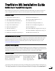
TracVision M5 Installation Guide MultiSat Control Panel (MCP) Configuration These instructions explain how to install the TracVision M5 satellite TV antenna system on a vessel. Complete instructions on how to use the system are provided in the User’s Guide. Installation Steps 1. Inspect Parts and Get Tools, 3 10. Wire the Switchplate, 12 2. Plan the Antenna Installation, 4 11. Wire the MCP and Receivers, 13 3. Plan the Belowdecks Installation, 5 12. Connect Power, 14 4.
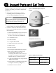
1 Inspect Parts and Get Tools Before you begin, follow these steps to make sure you have everything you need to complete the installation. Figure 1: TracVision M5 System Components Antenna a. Unpack the box and ensure it contains everything shown on the Kitpack Contents List. Save the packaging for future use. Radome IMPORTANT! Always lift the antenna by the baseplate and never by the radome or any portion of the internal antenna assembly (see Figure 1). Baseplate b.
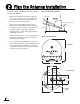
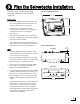
2 Plan the Antenna Installation Before you begin, consider the following antenna installation guidelines: • • Figure 3: Blockage from Obstruction Minimize blockage. The antenna requires a clear view of the sky to receive satellite TV (see Figure 3). The fewer obstructions, the better the system will perform. Make sure the mounting surface is wide enough to accommodate the antenna’s base (see Figure 4). Also make sure it is flat, level, strong enough to support the antenna’s weight (30 lbs, 13.
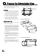
3 Plan the Belowdecks Installation Before you begin, consider the following installation guidelines for the belowdecks equipment. Figure 5: Switchplate Dimensions 4.39" (111.5 mm) Switchplate • Select a switchplate mounting location in a dry, well-ventilated area belowdecks away from any heat sources or salt spray. • Be sure to leave enough room at the switchplate’s rear panel for connecting the cables (see Figure 5 for switchplate dimensions).
4 Prepare the Belowdecks Sites Once you have identified suitable mounting sites for the switchplate and MCP, follow these steps to prepare the sites for installation. Figure 7: Switchplate Mounting Holes Layout 3.82" (97 mm) .32" (8 mm) Switchplate a. Using the switchplate mounting template provided at the end of this manual, mark and cut out a hole in the mounting surface to accommodate the switchplate (see Figure 7). b. Using the same template, mark the locations for the four switchplate mounting holes.
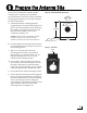
5 Prepare the Antenna Site Once you have identified a suitable antenna mounting site, according to the guidelines provided in Step 2, follow these steps to drill the mounting holes and cable access hole to prepare the site for installation. a. Unfold the antenna mounting template (supplied in the Customer Welcome Kit) and place it onto the mounting surface. Make sure the “FWD” (forward) arrow points toward the bow and is parallel to the vessel’s centerline (see Figure 10).
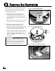
6 Remove the Restraints Inside the antenna, a foam block and two bolts prevent the antenna assembly from moving during shipment. Follow these steps to remove these shipping restraints. a. Remove the three #10-24 Phillips screws securing the radome to the baseplate. Carefully lift the radome straight up until clear of the antenna assembly and set it aside in a safe place.
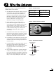
7 Wire the Antenna Follow these steps to connect the data, power, and RF cables to the antenna. a. First determine the number of RF coax cables required for your particular installation. If you wish to connect just one satellite TV receiver to the TracVision system, only one RF cable is required. If you wish to connect two or more receivers to the system, you need two RF cables. (See Figure 15 to determine the type of cable required.) b.
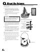
8 Mount the Antenna Follow these steps to mount the antenna to the mounting surface. Figure 18: “Forward” Arrow in Antenna Baseplate a. Place the antenna baseplate over the holes drilled in the mounting surface. Ensure the “Forward” arrow inside the baseplate points toward the bow and is parallel to the vessel’s centerline (see Figure 18). b. Make sure the four holes in the baseplate line up with the four holes in the mounting surface.
9 Modify the Switchplate (Optional) The switchplate comes preconfigured for a standard TracVision installation without an MCP. To configure the switchplate for an MCP installation, follow these steps to replace the maintenance port assembly in the switchplate with the MCP-ready maintenance port assembly supplied in the kitpack.
10 Wire the Switchplate Follow these steps to connect the switchplate to the antenna. Figure 24: Switchplate Wiring - Antenna Data Cable NOTE: System wiring diagrams are provided in Appendix F on page 35. a. First dress the data and power cables from the antenna. Strip back the insulation of each wire approximately 1/4" (6 mm) and gently twist each wire to ensure a good electrical connection. b.
11 Wire the MCP and Receivers Follow these steps to connect the switchplate to the MCP and the antenna to the receivers. Figure 26: MCP and Receiver Wiring a. Connect the main control cable (DB9-male to DB9-male) from the DB9 maintenance port jack on the switchplate to the “Antenna Unit” jack on the MCP (see Figure 26). Antenna b. Connect the RF control cable (RJ11 to DB9-female) from the RJ11 jack on the switchplate to the “RF Port” jack on the MCP. Power Data Switchplate c.
12 Connect Power Follow these steps to connect power. The switchplate supplies power to both the antenna and the MCP. Figure 27: MCP Power Plug Terminal Screw (x2) a. Before you begin, disconnect vessel power. CAUTION For your own safety, disconnect vessel power and make sure the circuit is dead before you connect any power wires. b. Route a set of power wires from the switchplate’s power output terminals to the MCP (for cable specifications, see Figure 2 on page 3).
13 Mount the Switchplate & MCP In Step 4, you prepared the mounting sites for the switchplate and MCP. Now follow these steps to mount them. Figure 30: Mounting the Switchplate Front Cover Switchplate Switchplate a. Drill four 5/32" (4 mm) holes in the countersunk settings in the switchplate’s support frame (see Figure 30). Mounting Surface a. Fit the switchplate assembly into the mounting hole until it is flush with the mounting surface. 5/32" ( 4 mm) Mounting Hole (x4) b.
14 Enter Your Latitude & Longitude Follow these steps to turn on the system and enter your vessel’s latitude and longitude. NOTE: The antenna will use your position information to speed up satellite acquisition. If the antenna knows where you are, it knows where it should start looking for the satellite. In addition, for a linear system, the antenna will use your position information to calculate the correct LNB skew angle. Figure 33: Switchplate Power Switch ON OFF Figure 34: Lat/Long Menus on MCP a.
15 Select Satellites Follow these steps to set up the system for the desired pair of satellites. Figure 35: Satellite Selection Menus on MCP IMPORTANT! Menu To select a three-satellite (Trisat) group for a linear system, see Appendix C on page 29. To select a DIRECTV HDTV three-satellite (Trisat) group, see Appendix A on page 23. a. Press the center MENU button on the MCP’s front panel to access the onscreen menu (see Figure 35). Install satellite? Yes Next Return Yes b.
16 Get the LNB Skew Angle (Linear only) To optimize reception, the antenna’s LNB must be set to the correct skew angle for the linear satellite(s) you want to track. Follow these steps to determine what the correct skew angle should be for the currently selected satellite and vessel position. TIP: You might also be able to get the correct skew angle from the customer’s satellite service provider. a. Press the center MENU button on the MCP’s front panel to access the onscreen menu (see Figure 36). b.
17 Set the LNB Skew Angle (Linear only) Follow these steps to set the antenna’s LNB to the skew angle you noted in Step 16. Figure 37: LNB Location on Back of Antenna’s Reflector a. Turn off and unplug the receiver(s). Reflector b. Disconnect antenna power at the switchplate. LNB CAUTION Disconnect power from the antenna and the receivers before you adjust the LNB. The antenna’s moving parts can cause injury. c. Remove the antenna’s radome, if you installed it earlier in Step 8e.
18 Educate the Customer The installation process is complete! Figure 40: Example of Satellite Blockage Before you depart the vessel, test the system to verify the antenna works properly. Then give the Customer Welcome Kit to the customer and explain how to use the system. Also be sure the customer understands the following: • Keep the radome installed on the antenna at all times. The radome protects the antenna’s moving parts from wind, rain, and debris.
Appendices This section provides supplemental instructions for special or advanced configurations. It also provides system wiring diagrams and mounting templates for the belowdecks equipment. Contents A. DIRECTV HDTV Installation, 23 B. Wiring 3+ Receivers (Circular only), 28 C. Selecting a Trisat Group (Linear only), 29 D. Satellite Library, 30 E. User-Defined Satellites, 31 F.
A DIRECTV HDTV Installation These supplemental instructions explain how to configure the system for DIRECTV HDTV using KVH’s optional HDTV converter. To complete a basic, single-receiver configuration, you will need the following components: • HDTV converter (KVH part #02-1431) • Splitter (KVH part #19-0366) • DIRECTV HD receiver • HDTV television The HDTV converter adjusts the signal frequency of DIRECTV’s 110 satellite, allowing the system to receive its high-definition channels.
A Continued... 6. If you wish to connect a second, standard (non-HD) receiver to the antenna, connect the RF2 cable from the antenna to the “Satellite In” jack on the secondary receiver. Figure 42: Wiring Multiple DIRECTV HD Receivers Antenna IMPORTANT! The HD receiver is the primary receiver that controls satellite selection. The secondary receiver will only be able to select a channel on the satellite that is currently selected on the primary HD receiver.
A Continued... 4. Connect an RF coax cable from the “RF Out” jack on the HDTV converter to the “LHCP +18V” jack on the multiswitch. 5. Connect an RF coax cable from the “Tone Detect” jack on the MCP to either of the “Out” jacks on the splitter. 6. Connect an RF coax cable from any output of the multiswitch to the available “Out” jack on the splitter. 7. Connect an RF coax cable from the “Input” jack on the splitter to the “Satellite In” jack on the primary HD receiver.
A Continued... Selecting the DIRECTV Trisat Group Figure 43: DIRECTV Trisat Group Selection Menus on MCP Follow these steps to turn on the system and set it up for Trisat mode. In Trisat mode, the system tracks and receives TV signals from three DIRECTV satellites (101, 119, and 110). The 110 satellite carries most of DIRECTV’s HD programming. Menu 1. Ensure the antenna has a clear, unobstructed view of the sky. Install satellite? Yes Next Return 2.
A Continued... Sat Select Modes In Automatic mode, the antenna automatically switches between a pair of satellites as the user changes channels on the receiver’s remote. The user sets the MCP to automatically switch between either 101-110 or 101-119 (see Figure 44). In Manual mode, the user presses a button on the MCP whenever he/she wishes to switch satellites. The user can select between 101, 110, and 119 (see Figure 45).
B Wiring 3+ Receivers (Circular only) Appendix IMPORTANT! Only antennas equipped with a circular dual LNB can support more than two receivers. Antennas equipped with a linear LNB support only two receivers. Figure 46: Multiswitch Wiring - Antenna with Circular Dual LNB Antenna To connect three or more receivers, follow these steps to install an active (powered) multiswitch between the antenna and the receivers.
C Selecting a Trisat Group (Linear only) Follow these steps to turn on the system and set it up for one of the three European Trisat groups: Trisat Group Satellites Europe WB HotbirdWB, Astra1, Astra2S Europe Hotbird, Astra1, Astra2S Scandinavia HotbirdWB, Sirius, Thor 1. Ensure the antenna has a clear, unobstructed view of the sky. 2. Apply power to the receiver(s), TV(s), and switchplate. Wait two minutes for startup. 3.
D Satellite Library Appendix The TracVision antenna can track a variety of DVB-compatible and DSS (DIRECTV) satellites. Most popular satellites are programmed in the antenna’s library (see the table below). North America Europe Standard Circular Dual LNB Required Linear Dual LNB Required Satellite, Longitude Name in Library Satellite Name in Library DIRECTV, 72°W DSS_72 Astra 1, 19.2°E ASTRA1 DIRECTV, 101°W DSS_101 Astra 2N, 28.2°E ASTRA2N DIRECTV, 110°W DSS_110 Astra 2S, 28.
E User-Defined Satellites The satellite library in the TracVision antenna includes two slots for user-defined satellites (USER 1 and USER 2). You can program one or both of these library slots for any satellite you wish that is not already set up in the library. Appendix Figure 48: Technician Programming the Antenna Connect a Laptop to the Antenna To program your user-defined satellite(s), you first need to connect a Windows® laptop computer to the TracVision system and start Windows HyperTerminal.
E Continued... 4. Apply power to the TracVision antenna. Data should soon be scrolling in your HyperTerminal window (see Figure 51). If no data appears, check your connections and make sure you’re using the correct COM port. Figure 51: Antenna Data Scrolling in Window 5. Follow the steps in the next section to program the antenna via the HyperTerminal window.
E Continued... Enter the following commands via Windows HyperTerminal or KVH Flash Update Wizard. 1. Type HALT then press Enter. 2. Type DEBUGON then press Enter. 3. Type the following SATCONFIG command then press Enter. Italics indicate a variable field (see Figure 53 for definitions). SATCONFIG,USERA,B,C,D,E 4. Type @DEBUGON then press Enter. 5. Type the following @SATCONFIG command then press Enter. Italics indicate a variable field (see Figure 54 for definitions). @SATCONFIG,F,G,H,I,J,K,L,M,N 6.
E Continued... Example - Linear Satellite Example - Circular Satellite The following is an example of programming a linear user-defined satellite (USER 1). The following is an example of programming a circular user-defined satellite (USER 1). Satellite Name: YOURSAT 123 at 7°W Satellite Name: YOURSAT 456 at 122°W Transponder Data Value Horizontal High Transponder Data Value Right Frequency 11.966 GHz Frequency 12.
F Wiring Diagrams This appendix provides system wiring diagrams for the following receiver configurations: • One or two receivers • Three or more receivers (circular only) • One DIRECTV HD receiver • Two or more DIRECTV HD receivers Appendix IMPORTANT! The wiring diagrams on the following pages are intended as a quick reference only. Be sure to follow the complete wiring instructions provided earlier in this manual.
F Continued...
F Continued...
F Continued...
F Continued...
.16" (4 mm) 2.36" (60 mm) 3.19" (81 mm) Panel Cutout 3.82" (97 mm) .32" (8 mm) (2.25 mm) 2.
.63" (16 mm) 3.08" (78 mm) 1.83" (46 mm) .63" (16 mm) 4x .136" (3.45 mm) 4x R .63" (16 mm) 7.62" (194 mm) 8.
KVH Industries, Inc. 50 Enterprise Center Middletown, RI 02842-5279 U.S.A. Phone: +1 401 847-3327 Fax: +1 401 849-0045 E-mail: info@kvh.com Internet: www.kvh.com © Copyright 2006 KVH Industries Inc. KVH Europe A/S Kokkedal Industripark 2B 2980 Kokkedal Denmark Phone: +45 45 160 180 Fax: +45 45 160 181 E-mail: info@kvh.dk Internet: www.kvh.com KVH and TracVision are registered trademarks of KVH Industries Inc.