
Control Panel Configuration Installation Guide TracVision M5


15
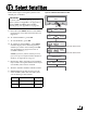
In Step 4, you prepared the mounting sites for the
switchplate and MCP. Now follow these steps to
mount them.
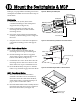
Switchplate
a. Drill four 5/32" (4 mm) holes in the
countersunk settings in the switchplate’s
support frame (see Figure 30).
a. Fit the switchplate assembly into the
mounting hole until it is flush with the
mounting surface.
b. Secure the support frame and switchplate
assembly to the mounting surface using four
#6 screws.
c. Snap the front cover onto the switchplate to
conceal the mounting screws and support
frame.
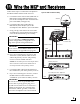
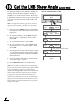
MCP - Velcro Mount Option
a. Clean the bottom of the MCP and the
mounting surface using a mild detergent.
b. Peel the backing from the two supplied
Velcro fabric squares and stick them to the
bottom of the MCP (see Figure 31).
c. Position the two Velcro hook disks onto the
mounting surface. Drill screw holes for the
disks and secure in place with #4-24 screws.
d. Press the MCP firmly into place so that the
fabric’s loop material engages the hook disks.
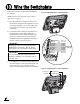
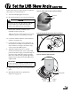
MCP- Flush Mount Option
a. Make sure the flush mount bracket is
attached to the MCP. If it is not attached,
disconnect all of the cables from the MCP,
attach the bracket as explained in Step 4 on
page 6, then reconnect the cables.
b. Insert the MCP and bracket assembly into the
mounting hole and secure in place with four
#8 screws and washers (see Figure 32).
Switchplate
5/32" ( 4 mm)
Mounting Hole (x4)
#6 Screw (x4)
Front Cover
Mounting Surface
Figure 30: Mounting the Switchplate
Fabric Strip (x2)
Hook Disk (x2)
#4-24 Screw (x2)
Figure 31: Velcro Mounting the MCP to a Horizontal Surface
#8 Screws and
Washers (x4)
Figure 32: Flush Mounting the MCP to a Vertical Surface
Mount the Switchplate & MCP
13