
Control Panel Configuration Installation Guide TracVision M5


19
Follow these steps to set the antenna’s LNB to the
skew angle you noted in Step 16.
a. Turn off and unplug the receiver(s).
b. Disconnect antenna power at the switchplate.
c. Remove the antenna’s radome, if you
installed it earlier in Step 8e.
TIP: If you keep the radome topside, secure it with
a lanyard to prevent it from falling overboard.
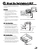
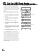
d. Locate the LNB on the back of the antenna’s
reflector (see Figure 37).
e. Loosen the two wing screws on the base of
the antenna’s feed tube, located in the center
of the reflector (see Figure 38). These wing
screws secure the LNB in place.
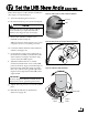
f. Adjust the LNB clockwise or counter-
clockwise until the skew arrow on the LNB
points to the skew angle you noted in Step 16
(see Figure 39).
If the skew angle is greater
than +15°, subtract 180 to get the equivalent
negative skew angle and set the LNB to that
angle instead.
g. Tighten the wing screws to secure the LNB in
place.
h. Reinstall the radome (as explained in
Steps 8e-f on page 10).
CAUTION
Disconnect power from the antenna and the
receivers before you adjust the LNB. The
antenna’s moving parts can cause injury.
Figure 37: LNB Location on Back of Antenna’s Reflector
LNB
Reflector
Wing
Screws
Reflector
Fi
gure
38
:
Wi
ng
S
crews
S
ecur
i
ng
t
h
e
LNB
to
t
h
e
R
e
fl
ector
0 Skew
Positive
Skews
Negative
Skews
LNB
S
K
E
W
Choke Feed
Figure 39: LNB Skew Angle Adjustment
Be sure to keep the LNB fully inserted into the
choke feed to ensure optimum performance.
IMPORTANT!
Set the LNB Skew Angle (Linear only)
17