
Control Panel Configuration Installation Guide TracVision M5


25
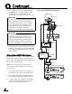
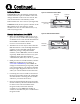
4. Connect an RF coax cable from the “RF Out”
jack on the HDTV converter to the “LHCP
+18V” jack on the multiswitch.
5. Connect an RF coax cable from the “Tone
Detect” jack on the MCP to either of the
“Out” jacks on the splitter.
6. Connect an RF coax cable from any output of
the multiswitch to the available “Out” jack on
the splitter.
7. Connect an RF coax cable from the “Input”
jack on the splitter to the “Satellite In” jack on
the primary HD receiver. This receiver will
control satellite selection.
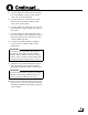
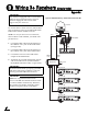
8. Connect any additional HD or standard
receivers to the available outputs of the
multiswitch.
9. Terminate any unused multiswitch outputs
with 75 ohm DC blocks (Channel Master
#7184, Radio Shack #15-1259, or equivalent).
10. Follow the instructions in Steps 12 and 13 on
pages 14-15 to connect power and mount the
switchplate and MCP. Then skip to page 26 to
select satellites.
The receiver you connected to the splitter is
the primary receiver that controls satellite
selection. The secondary receiver(s) will only
be able to select a channel on the satellite that
is currently selected on the primary receiver.
IMPORTANT!
Be sure the multiswitch is properly grounded.
With the multiswitch grounded, you do not
need to ground the individual receivers.
IMPORTANT!
Continued...
A